Hi, I built a 100watt guitar amp using 4 EL34 power valves and I am still in the process of fault finding. I had swapped round the phase of the push pull output in order to get nagative feedback as opposed to positive feedback!
As a routine check after this I checked the bias. My figures might be slightly out because I don't have them on me now, but originally i biased the amp at -37V and it seems now be biased at -45V. Can this be considered at all normal for new valves? If not then it is confusing me a lot and I can not see what else could be wrong because nothing else has been touched since the bias was previously set around May this year.
Another point possibly worth mentioning is that all the bias voltages drifted exactly the same amount.
Thanks for any help anybody can offer!
Chris
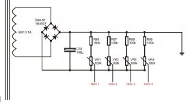
Well I've only actually been using two valves to avoid wrecking all 4 in the event that something went wrong - so the bias voltage was the same incorrect value for two of the valves. I have attached the schematic of the bias supply - not a lot to see really. I think its unlikely to be the cap because it was brand new and sprague tend to be fairly reliable.
How much drift is actually normal? The valves are cryogenic svetlana winged C's and I haven't checked them since I first put them in so its possible that they drifted within the first few hours of use.
Cheers
How much drift is actually normal? The valves are cryogenic svetlana winged C's and I haven't checked them since I first put them in so its possible that they drifted within the first few hours of use.
Cheers
Attachments
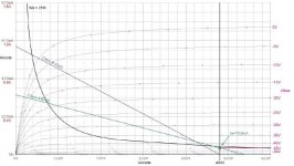
I've attached the anode curves I drew when designing the amp and the valves are pretty close to their max rating but more interestingly according to these I should be reading -45V anyway  ! This conflicts with what I wrote down when testing the amp of -37V. I think for the time being since my records don't agree, I will ensure they are at a correct value and monitor them so see if anything happens. It looks quite possible that they are exactly the same as they were when I set them.
! This conflicts with what I wrote down when testing the amp of -37V. I think for the time being since my records don't agree, I will ensure they are at a correct value and monitor them so see if anything happens. It looks quite possible that they are exactly the same as they were when I set them.Attachments
I think it is my bias voltage - I need to study my circuits a bit to find out where I'm going wrong. Not worked on it for a while and I think that's the problem! Having looked over my circuit diagrams i was measuring the bias voltage - but it's possible that the cathode current (which I have a 1ohm resistor in series with to measure) is what I intended to measure.
Based on the circuitry you've drawn, and depending on where you measured it the bias voltage drift you mention has absolutely nothing to do with the tubes themselves.
A leaky capacitor has nothing to do with the increase in bias potential either - in absolute terms -45V is higher than -37V. So the cap is not leaking.
A couple of thoughts come to mind:
1. The day you set the bias the mains voltage was (very) low. (Or you set it while you had the amplifier connected to a variac or ballast lamp. (current limiter)
2. Did you use the same meter to measure the grid bias voltage in all instances or have you changed meters for one that is more/less accurate than before.
3. Component drift - are your resistors and pots adequately rated for the power they are dissipating? If not they may have drifted in value.
Last edited:
Hi Kevin,
1. This sounds like a reasonable explanation that the mains voltage was low - I have noticed it change quite a lot within the limits it is allowed so tomorrow I shall check the bias and the mains voltage and see the correlation.
2. I have been using the same meter so this shouldn't affect readings
3. The components I have used are all generously overated and brand new (2W resistors and caps easily within limit)
Looking at my anode curves, if the bias voltage was -37V then the valves would be running outside their limits, and since I have seen no red plates or any other spurious signs, I think it may well merely be a clerical error!
Once again browsing through my dissertation on the topic, it turns out the current should be ~37mA and bias voltage -45V:
"Seventy percent of the max dissipation of the valves is considered a safe maximum bias point and it is not recommended to stray far beyond this for a class AB amplifier. A result of 72.9mA was obtained from Equation 3.4.1 and this is marked on Figure 3.4.3. This value tells us that when setting up and testing the amplifier that each valve should have an anode current of 36.5mA and a bias voltage of ~44V."
These values seem a bit too similar to the one's I was confused about and too much so to be coincidental! I will make the necessary checks mentioned but most things seem to point at this being the problem!
- Status
- This old topic is closed. If you want to reopen this topic, contact a moderator using the "Report Post" button.
- Home
- Amplifiers
- Tubes / Valves
- Bias Drift