Here is a design for driving a Power Valve at the highest level of sound quality!
I have been using a similar circuit since 2005 to drive my 300B-SE. The sound is better all-round than any circuit I could find using triodes or pentodes. Compared to the usual 6SN7 cascade (ac or dc coupled) the sound is much more immediate and articulate (can hear lyrics much easier).
Pentode drivers work well too, but the power supply needs about 10 stages of LC filtering to be quiet enough.
This circuit has been designed to work with the Schade-connected antitriode project that we are working on here:
http://www.diyaudio.com/forums/tube...chade-pp-anti-triode-ecl86-4.html#post1947843
but it will work with many others. It will drive loads all the way down to 1K or less, and it takes 1nF to roll the response off at 20kHz with a 2K ohm load.
It will drive our EL84 Schade-connected amp to near full output with only 0.3% THD - almost all is 2nd harmonic.
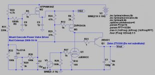
The circuit is a shunt cascode in architecture.
The TL431 3-pin chip regulates the screen voltage of the output valve, and uses this 210V for a supply voltage. At the same time, the circuit regulates the current source M5, and the cascode voltage via Q1.
The performance of shunt cascode transistor Q1 is important, please try to use the ZTX558 here. MOSFETs have too much capacitance and/or too little gm (remember that hole mobility is lower than electron mobility, so P-channel FETs are much worse the N-channel). The ZTX558 has 400V and 1W handling; flat hfe, but only 5pF Cob. BJTs are the best (upper) cascode device, due to their high gm.
The current source feeds 20mA into the anode circuit, which is pinned to 100V by Q1. the excess current rolls into the output as a class A offset.
The E88CC is designed for cascode duty, and is a perfect fit here. With a fixed 100V anode the valve can operate at its most linear region - hence the very low distortion, and fine sound. A current production valve seems a good idea too.
Other advantages: The input AND the output are referenced to ground, so the loop areas (EM moment) can be reduced greatly. This also means the power supply rejection is hugely better than ordinary cascodes, or pentodes, and is better even than low-Z triodes.
There is no signal current in any electrolytic capacitor (not even the supply cap).
I have been using a similar circuit since 2005 to drive my 300B-SE. The sound is better all-round than any circuit I could find using triodes or pentodes. Compared to the usual 6SN7 cascade (ac or dc coupled) the sound is much more immediate and articulate (can hear lyrics much easier).
Pentode drivers work well too, but the power supply needs about 10 stages of LC filtering to be quiet enough.
This circuit has been designed to work with the Schade-connected antitriode project that we are working on here:
http://www.diyaudio.com/forums/tube...chade-pp-anti-triode-ecl86-4.html#post1947843
but it will work with many others. It will drive loads all the way down to 1K or less, and it takes 1nF to roll the response off at 20kHz with a 2K ohm load.
It will drive our EL84 Schade-connected amp to near full output with only 0.3% THD - almost all is 2nd harmonic.
The circuit is a shunt cascode in architecture.
The TL431 3-pin chip regulates the screen voltage of the output valve, and uses this 210V for a supply voltage. At the same time, the circuit regulates the current source M5, and the cascode voltage via Q1.
The performance of shunt cascode transistor Q1 is important, please try to use the ZTX558 here. MOSFETs have too much capacitance and/or too little gm (remember that hole mobility is lower than electron mobility, so P-channel FETs are much worse the N-channel). The ZTX558 has 400V and 1W handling; flat hfe, but only 5pF Cob. BJTs are the best (upper) cascode device, due to their high gm.
The current source feeds 20mA into the anode circuit, which is pinned to 100V by Q1. the excess current rolls into the output as a class A offset.
The E88CC is designed for cascode duty, and is a perfect fit here. With a fixed 100V anode the valve can operate at its most linear region - hence the very low distortion, and fine sound. A current production valve seems a good idea too.
Other advantages: The input AND the output are referenced to ground, so the loop areas (EM moment) can be reduced greatly. This also means the power supply rejection is hugely better than ordinary cascodes, or pentodes, and is better even than low-Z triodes.
There is no signal current in any electrolytic capacitor (not even the supply cap).
Attachments
Folded cascode... Neato circuit for sure, but not new.
Putting it together with a shunt regulated servo loop,
that part of it certainly merits attention.
PSRR is indeed excellent, if ref'd only to ground level.
But the circuit you propose to drive is noise ref'd to B+
and floats upon a CCS to GND. How do you propose to
cross the incompatible rail references?
Last edited:
I tried a few ways of dc-coupling to the EL84 circuit, but they all made a mess of it one way or another.
I imagine in this case that the EL84 anode to grid resistor will be 100K, and have a dc coupled 12~15K resistor from the driver output to ground. cap coupling to the EL84 grid.
The current (signal) source in the power amp circuit is this driver - just remove the 100p/2K from the output of the driver, and connect up.
At least there will then be a low impedance to ground, if not exactly ground reference at the EL84 input side.
Hi Rod,
10 stages of LC-filtering needed for a pentode driver to meet your demands on what is "quiet", eh?
Regards,
Tom Schlangen
Pentode drivers work well too, but the power supply needs about 10 stages of LC filtering to be quiet enough.
10 stages of LC-filtering needed for a pentode driver to meet your demands on what is "quiet", eh?
Regards,
Tom Schlangen
Hi Rod,
10 stages of LC-filtering needed for a pentode driver to meet your demands on what is "quiet", eh?
Regards,
Tom Schlangen
Tom, OK - I'm making an allowance for the G2 supply filter!
but seriously, it is not so much noise as the sound quality overall. Sound improved very much when the pentode driver mains trafo was upgraded from 150VA to 400VA. (even with 4 stages of LC/CMC filtering, and 6X4 rectifier). The pentode supply was not shared with the power valve - only 2 x 10mA pentodes.
Allen, well, I haven't heard the name 'inverted cascode' until now!
It's a shunt cascode because the cascoding transistor (Q1) shunts the excess current into the output - as opposed to the regular cascode, where the corresponding device is a series element.
Or, to think of it another way, the output device (Q1) is shunting the input device (the valve) in action. In the normal cascode, the device relationship is series.
The shunt action is what distinguishes it from normal cascodes in terms of performance - especially supply noise immunity (PSRR), and referencing the output to ground (rather than B+).
The name is an attempt to illustrate its action.
Re: shunt cascode
I've seen similar type SS cascodes referred to as folded cascodes.
Re: Ken: "PSRR is indeed excellent, if ref'd only to ground level.
But the circuit you propose to drive is noise ref'd to B+
and floats upon a CCS to GND. How do you propose to
cross the incompatible rail references?"
How about using an attenuating current mirror in the Schaded "triode's" plate circuit (at the B+ terminal) instead of the Schade feedback resistor. The grid summing node is summing currents anyway. Then the grids and gates can be ground referenced in the anti-triode stage. I guess this would make the feedback sensitive to load Z, giving a high output Z.
Guess one is back to a hum bucking resistor somewhere and using a normal Schade resistor.
Don
Last edited:
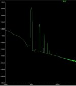
Did a quick sim of the folded cascode before going to work. Not so encouraging, but my sims involve some guesswork. The folded version has lower sensitivity and a lot higher THD then the CCS´d single tube. And the BJT is random choice.......
So maybe more current throught the BJT? Now is 40mA through the CCS with 15 of them through the E88CC.
. The folded version has lower sensitivity and a lot higher THD then the CCS´d single tube. And the BJT is random choice.......So maybe more current throught the BJT? Now is 40mA through the CCS with 15 of them through the E88CC.
An externally hosted image should be here but it was not working when we last tested it.
Lars, the 2K load resistor in my schematic is there to represent the Schade network load! so you can rearrange R23 to be the load (connect to ground) and delete the 2K.
With 100K/15K Schade resistors, the class A currrent through the shunt cascode transistor should be about 3mA
Check the smulation to see that your FET current source is completely stable under load - should vary only 0,1 or 0,2mA (from memory)
My PC doesn't have enough RAM to simulate the whole circuit (or something else is wrong!!)
Lars, the 2K load resistor in my schematic is there to represent the Schade network load! so you can rearrange R23 to be the load (connect to ground) and delete the 2K.
Then it makes sense
! Had my suspions but now we are back to the original Schade. And I didn´t read your last post from yesterday. Spontaneously 3mA seems a little on the lean side considering the load of ca 2k(AC)//15k(DC)? But I haven´t yet calculated the swing needed for full output..... One gets lazy when using LTSpice
!How about connecting the output stage Schade feedback resistor back to the driver R9/M5 source point. That would keep the B+ referenced feedback isolated to the B+ referenced current source. Hi Z between B+ references and ground references that way. Haven't seen anyone use a modulated current source for feedback before, but I don't see why not. The current fed back has unity gain through both M5 and Q1, so it's just like connecting to the original tube summing point. Might want to run the top end of R9 up to B+ then, instead of +Vg2.
Don
Don
Last edited:
How about connecting the output stage Schade feedback resistor back to the driver R9/M5 source point. That would keep the B+ referenced feedback isolated to the B+ referenced current source. Hi Z between B+ references and ground references that way. Haven't seen anyone use a modulated current source for feedback before, but I don't see why not. The current fed back has unity gain through both M5 and Q1, so it's just like connecting to the original tube summing point. Might want to run the top end of R9 up to B+ then, instead of +Vg2.
Don
Don, Could well be worth a try during the build (I certainly intend to make one)!
A potential advantage of this is to use low resistance values, and reduce phase effects, perhaps. Balance that against phase effects of feedback between stages vs. same stage.
We have to keep the current source referenced to VG2, though, or the current regulation will be degraded, or lost.
Rod,
My error - I meant to describe your circuit as a "folded cascode" as others have also described it - but I called in an "inverted cascode". Simple brain fade...
Your term - have you seen it used elsewhere - or is it your invention?
Regards, Allen (vacuum State)
Allen, I've heard of 'folded cascode' in the op-amp world, and always thought it a peculiarly unexpressive phrase.
I may have picked this up from reading too many copies of 'Wireless World/Electronics World' where feedback architectures were always distinguished among 'series' or 'shunt'. If I didn't get it there, I must have coined it! Either way, I fight shy of phrases that don't don't properly explain themselves, fearful obfuscating taxonomy or tenebrous lexicography and the like
I think there's a committee somewhere thinking up unhelpful stuff like this. In England, the type of mains circuit-breaker that cuts out when current in the Line conductor exceeds current in the Neutral is called a 'Residual Current Device'.
- The current involved is not 'Residual', and nothing else in the phrase tells you anything about what the damn thing does! I believe it's called a 'Interrupteur Différentiel' in Francophone countries - which needs no further explanantion...I think this ends up behaving as a folded concertina?
It folds upon an emitter, just like yours, sorta...
Except its also a phase splitter with two outs of
roughly matching DC, suitable for direct couple.
PSRR on the inverting cathode prolly ain't gonna be
optimal unless you upgrade the long neck to a CCS.
But doing so seems simple enough...
I'm also uncertain if the cathode impedances are
really equal? The inverting cathode (on the right)
may be forced by sand to mimic plate impedance
of the triode on the left???
Oh, and I forget a 220K in series with the collector
to keep the thing safe on cold start.
Attachments
Last edited:
Antoher highly interessent aspectoid bout this thingie...
I just realized both Cathode DC Voltage are directly
proportional to long neck CCS! Grid bias will float up
or down as necessary to maintain that relationship.
Thus cathode voltage is a known, given, constant.
Not something I have to worry might float around.
And I can tweak both at once, merely by adjusting
the neck. Somehow, I thinkn thats gonna prove to
be darn useful.
NPN shunt device
Hi all
With reference to Rod's original tube-ccs-shunt circuit: assuming B+ is quiet enough, could an NPN shunt transistor be used with load resistor to B+ instead of ground?
Second question: what if shunt outputs were generated both ways simultaneously and both capacitatively coupled (summed) to the next stage? Any obvious benefit or problems?
Rgds
Sheldon
- Status
- This old topic is closed. If you want to reopen this topic, contact a moderator using the "Report Post" button.
- Home
- Amplifiers
- Tubes / Valves
- Shunt Cascode Power Valve Driver