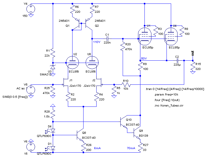
Ok... I'd love to hear your comments about the following design idea.

What I'm shooting for is an OTL headphones amplifier suitable for all loads (from 32R to 600R) and using cheap, easy to find tubes (the PCL805 is what I've got in mind).
The input is a quite conventional ltp made of matched jfets, with CCS, current mirror and cascoded with triodes.
The output stage is a pair of triode strapped pentode sections atop of a CCS. The 70ma running through the output stage should take care of the low impedance headphones nicely (of course the fun will be in the 150V/200mA B+).
I know the design is awfully "solid state" oriented with lots of feedback but, thanks to feedback, it gives a decent output impedance into low impedance headphones. I wouldn't put too much faith into simulations but, for 10Vp-p into 300ohms @10Khz, the THD is at 0.0025% and the FFT in ltspice is quite nice, with H2 -80db, H3 -83db, H4 -107db, H5 -120db. Stability appears good but it has to be built to really know.
I've some concerns though, related to start up. Should I fear for the jfets well-being ? Other concerns relate to matching. The PCL805 come with one triode and one pentode. There will be some mismatch thus. Will it be a worry (I'd think not but...) ?
Thanks in advance for any comments. Just don't shoot me down for mixing jfet, bjt and tubes

Attachments
Will the zener noise (U3) you're injecting in the triode grids be cancelled?

Hum... add an RC filter ?
I designed an otl headphone amplifier with 5687 srpp driver and 5842 configured in a White CF with no global feedback. No noise issues, and thd levels that were quite low into 64 ohm headphones/resistors.
I no longer have any data for this amplifier, but IMO with the right topology and tube choices you can design a headphone amplifier with excellent linearity and noise performance without global feedback. You might want to give it a shot.
That zener should be filtered with a first order low pass to the grids of your cascode.
One other concern is the 220uF capacitor, if it fails while you have your headphones on it will hurt!
Thanks at first for replying, it gives me something to think about 
Actually, the starting point for this design was the audiovalve RKV, an amplifier I've had and -stupidly- sold. It uses an opamp with a tube output stage enclosed in its feedback loop (made with pcl805 actually). One thing that was great (imo) was that it was almost completely insensitive to tuberolling. See http://www.jogis-roehrenbude.de/Verstaerker/PCL805-KH-Amp/PCL805-KH.htm So I thought... why not having the amp itself being an opamp and, while I'm at it, exchanging push pull for SE output.
Feedback would also help to diminish the output capacitor impact, an output capacitor quite unavoidable in OTL designs.

I don't doubt it. There are plenty of good designs for headphones around along those lines and those I've heard usually sounded real good. I must say that I'm seriously considering something like you did with 6n1p and 6n6p.I designed an otl headphone amplifier with 5687 srpp driver and 5842 configured in a White CF with no global feedback. No noise issues, and thd levels that were quite low into 64 ohm headphones/resistors. I no longer have any data for this amplifier, but IMO with the right topology and tube choices you can design a headphone amplifier with excellent linearity and noise performance without global feedback. You might want to give it a shot.
Actually, the starting point for this design was the audiovalve RKV, an amplifier I've had and -stupidly- sold. It uses an opamp with a tube output stage enclosed in its feedback loop (made with pcl805 actually). One thing that was great (imo) was that it was almost completely insensitive to tuberolling. See http://www.jogis-roehrenbude.de/Verstaerker/PCL805-KH-Amp/PCL805-KH.htm So I thought... why not having the amp itself being an opamp and, while I'm at it, exchanging push pull for SE output.
Feedback would also help to diminish the output capacitor impact, an output capacitor quite unavoidable in OTL designs.
No doubt about it. And I should add grid stoppers for the pentodes.That zener should be filtered with a first order low pass to the grids of your cascode.
For sure ! I keep a pair of rifa peh169 220uF/350v for that position. But how did you do it with your WCF ? Didn't it have an output cap sitting at 100V (assuming a B+ of 200V) ? Some kind of dc output protection has to be installed.One other concern is the 220uF capacitor, if it fails while you have your headphones on it will hurt!

As has been mentioned before, the main weakness is connecting that Zener directly to the grids of that cascode. I wouldn't rely on its AC impedance to ground the grids, and Zener noise is a lot more objectionable than gas discharge noise. Since the grids aren't pulling any meaningful current, definitely stick an RC filter in there.
As for making solid state play well with hollow state, separate the heater power from the HV DC. That way, you can preheat the cathodes before hitting 'em with the HV. That way, everything is good to go, and nothing gets overvolted because of cold cathodes.
As for how it'll sound, it's another case of try it. It'll sound excellent, good, indifferent, bad, or just plain
An externally hosted image should be here but it was not working when we last tested it.
. No way to tell from looking at a schemo.This circuit will not work in real life. Firstly, the voltage at the plate of U8 (labelled 110V) has no mechanism to define it.
This topology (current mirror 'loaded' long tail input pair) is only workable in completely directly coupled designs (ie. op-amps) where the DC operating points are stabilised by the global negative feedback loop.
The only way this circuit could be made to work is if a LTP-steering servo with a voltage reference is introduced to both sense and maintain the DC potential at the plate of U8 at your 110V.
The cascode zener noise is a practical non-issue also. The noise voltage that makes it to the drains of the jfets is largely rejected due to the LTP’s inherent PSR and what makes it through is then presented to the current mirror as a common-mode signal and cancelled. Bypassing the zener wont do any harm, but don’t expect to measure any significant difference in output noise if you ever get a working version of this circuit up and running.
Last edited:
This circuit will not work in real life. Firstly, the voltage at the plate of U8 (labelled 110V) has no mechanism to define it.
This topology (current mirror 'loaded' long tail input pair) is only workable in completely directly coupled designs (ie. op-amps) where the DC operating points are stabilised by the global negative feedback loop.
The only way this circuit could be made to work is if a LTP-steering servo with a voltage reference is introduced to both sense and maintain the DC potential at the plate of U8 at your 110V.
The cascode zener noise is a practical non-issue also. The noise voltage that makes it to the drains of the jfets is largely rejected due to the LTP’s inherent PSR and what makes it through is then presented to the current mirror as a common-mode signal and cancelled. Bypassing the zener wont do any harm, but don’t expect to measure any significant difference in output noise if you ever get a working version of this circuit up and running.
Strange, I have built very similar circuits and ran them open loop with no real problems, matched fets and reasonably matched tubes being all that was required. The voltage on the plate of U8 can (will) probably vary 10% from prediction likely without a serious problem ensuing. The currents are mirrored so that same current will flow through both the fets and the tubes, the bias on the grid constrains the spread of likely cathode voltages to those likely at the resulting operating point, so while in terms of dc it is not entirely predictable, I expect the AC performance/balance should be ok. Not my choice to mix so much sand with tubes, but I see no reason why it would not work with some careful tweaking. IMO A simpler circuit would probably sound better, but this one should work.
Strange, I have built very similar circuits and ran them open loop with no real problems, matched fets and reasonably matched tubes being all that was required. The voltage on the plate of U8 can (will) probably vary 10% from prediction likely without a serious problem ensuing. The currents are mirrored so that same current will flow through both the fets and the tubes, the bias on the grid constrains the spread of likely cathode voltages to those likely at the resulting operating point, so while in terms of dc it is not entirely predictable, I expect the AC performance/balance should be ok. Not my choice to mix so much sand with tubes, but I see no reason why it would not work with some careful tweaking. IMO A simpler circuit would probably sound better, but this one should work.
That is strange. The plate impedance of U8 here is too high. It would only take a very small current imbalance to throw the DC potential way out (towards the rails). If this was my design, I'd insert a 2nd voltage amplification stage and directly couple the whole thing.
Thank you, Kevin and Glen, for the cold shower; it was needed  I must say that thinking twice about it (with my God-given-brain and not with my simulator), Glen's point about the unclear DC operating point makes a lot of sense. Even if it can be made to work in real life, I'd rather not deal with a very temperamental amp.
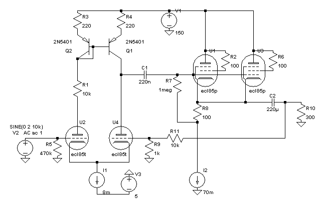
I think I will simply go for the input stage developped here : The SOHA II Headphone Amplifier , to which I'll add the cathode follower instead of their SS output stage. I'd run more current through the common cathode input stage though. The triodes can stand 3 or 4ma with around 100V from cathode to plate. Of course, the gnfb will be on the low side... I've yet to fix the actual details of this.
That'd give something like this, which seems easier to get right:

I'll keep the output cap. I feel, maybe wrongly, safer with it than with a servo of some kind.
I think I will simply go for the input stage developped here : The SOHA II Headphone Amplifier , to which I'll add the cathode follower instead of their SS output stage. I'd run more current through the common cathode input stage though. The triodes can stand 3 or 4ma with around 100V from cathode to plate. Of course, the gnfb will be on the low side... I've yet to fix the actual details of this.
That'd give something like this, which seems easier to get right:
I'll keep the output cap. I feel, maybe wrongly, safer with it than with a servo of some kind.
Attachments
- Status
- This old topic is closed. If you want to reopen this topic, contact a moderator using the "Report Post" button.
- Home
- Amplifiers
- Tubes / Valves
- Headphones amplifier with highish gnfb

