No. Those are stiff PCB material but they are hjust used as a place to anchor the posts used to make the P-P very tidy. This layout is also very important. I have a pair of these boards assembled, if i find them i can take some pictures. I was Allen’s Mac support guy for a long time and i got paid with an RTP kit (no PS unfortunately — have the parts, just haven’t put it together).
I talked to Vacuum State after Allen’s untimely demise, so my eatlier PCB comment was postAllen. AFAIK they are still making these.
dave
The unit reviewed at Six Moons definitely has PCBs with tracks.
Alex
To end all guessing and speculation:
We switched to PCB when we learned what makes a PCB-based circuit sound good. Although all our PCB-based modules are handbuilt this still provides a vast advantage in productivity, minimizing errors and misshaps over p-p.
Coming to sonics the differences between p-p and PCB are subtle, but there. But you need a very good sonic memory or an A-B comparison to point your finger on it.
As always in all technical devices it's a trade off between performance, cost, reliability and a lot of other circumstances.
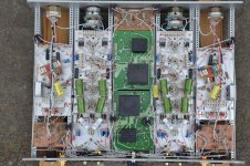
We won't offer PCBs for DIY as we want them to use in our finished products only. In the pictures above you also see a different SuperReg, that's what we call a SR Gen II and is also for readybuilt units only.
Regards
Thomas
Vacuum State GmbH
We switched to PCB when we learned what makes a PCB-based circuit sound good. Although all our PCB-based modules are handbuilt this still provides a vast advantage in productivity, minimizing errors and misshaps over p-p.
Coming to sonics the differences between p-p and PCB are subtle, but there. But you need a very good sonic memory or an A-B comparison to point your finger on it.
As always in all technical devices it's a trade off between performance, cost, reliability and a lot of other circumstances.
We won't offer PCBs for DIY as we want them to use in our finished products only. In the pictures above you also see a different SuperReg, that's what we call a SR Gen II and is also for readybuilt units only.
Regards
Thomas
Vacuum State GmbH
Hello !
I have a RTP 3 kit with werk-nr 3. One of the first kit sold.
I had a acident a short time after it was finished. When I repaced the eksisting volum pot to Elma stepattunators, I forgot to replace the teflon strips between S-reg and chassi that had fallen off during working. When turning on there was a short and the amplifier was no longer in operationel condision.
I placed it in the closet, and it stayed for about 15 years. A few years ago my lifesituasjon had changed a bit, and the interest for Diy had started to come back. I took it out and looked at for possible repair . After studying it a while, I came to a conclusion that I did not have the experience to find the errors and do the repair. It was gone to many years and I didnt knew it any more. I contacted Vacuum State, but they did not repair kit.
I bought 2 New S-reg and after advice from Thomas on VSE I started to check the - 24 v mini reg and ccs. The first ting that hapened was that the fuse of my digital volt meter blow. I then tryed to be very carefull to not tutch any unwanted parts, still the meter vent out, this time not the fuse but the meter was broken. Sadly this was a 100 Euro Appa unit.
At that time a gave up and desided to get a qualified person to do the repair. After a wile I came in contact With a person and come to a understanding that I should solder the S-reg my self, and bring him amplifier, Sreg and shematics.
During this Christmas I soldered the Sreg, and by a coinsident I googled the RTP3, and some realy Nice Picture of Diy Rtp3 came up. I followed the picture and ended up her on Diyaudio. After Reading and compairing some of the nice work her to mine, I felt that mine was ok when looking at single parts. But as a houle, my unit clerly looked homemade. I then got the feeling that it was bether to rebuild it than spend monney on repair. Since I got litle work to do this Winter I desidet to go for it.
I post her, and continuing writing on next post.
The nice thing about the RTP3 is that it is modular - both physically, where you have the phono, line and SuperReg modules clearly separated, and functionally, in the sense that the zero global feedback topology means that you can test each stage independently.
For this reason, I suggest that you take your time, and systematically test each part of the circuit one after the other. Do you have the full set of schematics and instructions?
The first step is to check all PSU voltages are as intended, bearing in mind that the B+ will be higher than expected into an open circuit. Second, make sure the SuperRegs are working, ideally into a dummy load - I remember using something like 5K-6K, capable of dissipating at least 20W.
From then on, it's up to you (with the usual warnings about high voltage and personal safety).
Alex
I am now finnish rebuilding, and have started to test it.
When I Connect a 5K resistor in Power supply, between + and gnd on B+, I have 415 vdc.
Is this a litle high volt to feed Sreg, if thinking optimum ?
Would it be a good idea to have a resistor between Power supply and Sreg to take some of the heat. Or should the Sreg handel it all ?
When I bought the kit I was given a scetch of how to implement a Mat 02 in the phono section from Allen Wright. It showed that the 47k resistors from + and - signal in, should be bypassed by 330 pF cap. On the phono shematic posted here on diyaudio, they are not included. When I look at the partslist of the phonostage,4 x 330 pF are inkluded. What is the correct here ?
In the 2008 build descripsion of the line stage there are a few changes from my unit. On tube B out from the grids between the 100 ohm resistors ( 50 V ) the 51 k is changed to 56 k. The 249 k is changed to 2x 100 k ( 200 k )
In the end section the 121 k are replaced With 100 k. The 121 k was connected to gnd, but the 100 k have 1 k between them and gnd.
It looks like the 2,7M are changed to 2x 1 M (2M), and some og the 1,5 M are changed rosss 1 M. In the correction on the 2004 build description some 1M are changed to 1.5M. But her its back again ? I only have the building description and it sems to contain some errors. I dont feel confident on using that as correct information. Is there a full shematic on this circuit to se some where.
What is the gain by doing this change ?
My first kit build was the Atma-Sphere M-60 OTL amplifier. This was about 1997 -98. They had a owners grop (asog) On that webside there was a page were all the Upgrades from both the users and Atma-Sphere was listed for all to see. Is there somewhere a side were People have listed up Upgrades on the Rtp3 ?
Becouse of the coronavirus, all most everything is closed, and I have now even more spare time. It woud be Nice to spend some of it on the amp. I have seen sugestion that solder 2x 0,1 uf from each heater pin to gnd is improvment. Have sombody tryed it ore is it only teoreticly ?
The last thing !
I have photos of my unit inside / outside and Power supply. I would like to post Picture, but dont understand how to do it. Can someone please explain.
Sincerely
Frode
Last edited:
Hello Alex !
Thanks for Your reply.
I have a 5k 150 w resistor, so it should give me some time") But this is also getting very hot after a few minutes.
But this is also getting very hot after a few minutes.
The B+ transformer are the one from the kit, and it have been used before for some time without problem. I just wanted som inputs about it before conecting the Sreg to it. It might have been some changes since my kit came out.
Frode
Thanks for Your reply.
I have a 5k 150 w resistor, so it should give me some time
But this is also getting very hot after a few minutes.The B+ transformer are the one from the kit, and it have been used before for some time without problem. I just wanted som inputs about it before conecting the Sreg to it. It might have been some changes since my kit came out.
Frode
I have a 5k 150 w resistor, so it should give me some time
Is this voltage on the unregulated DC (415V), or on the output of the SuperReg? This makes a big difference! 300x300/5000=18W, while 415*415/5000=34.4W!
My SuperReg has 350V input for 300V output, by the way, and I think anything over 400V input would be stressing the regulator more than it needs.
Alex
Hello Alex !
It is in the separate power supply, with a 5k load installed. ( before the Sreg )
For the Sreg to reduse 115 v I gues that will create a lot of heat in the Sreg. My thinking was that it maight be a good idea to install a resistor between the PS and Sreg to take of some of the volt and also some of the heat ?
Last edited:
Hello Alex !
It is in the separate power supply, with a 5k load installed. ( before the Sreg )
For the Sreg to reduse 115 v I gues that will create a lot of heat in the Sreg. My thinking was that it maight be a good idea to install a resistor between the PS and Sreg to take of some of the volt and also some of the heat ?
Attachments
Attachments
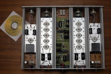
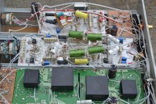
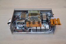
Her is a few pictures of my unit.
It only worked for me by quoting my self.
Sincerely
Frode
Attachments
Hi Frode,
Are those 3 aluminum clad resistors supposed to be the dummy load? If yes, this kind of resistor is supposed to be mounted on a heatsink in order to reach the designated power dissipation.
Hello,
AND if you mount them on a chassis they will need a piece of metal that will be close to the dimensions of your chassis for one resistor. If i remember well it was something like 300*300*1,5 mm aluminium. It will give a big bang when it dies. I have seen it once.
Greetings, Eduard
Hello !
Thank you for the advice. The 3 pieces of 15 k 50 w resistors are connected in parallel and are made to one 5 k 150 w resistor. They are drawing about the same amount of mA from the power supply as all the tubes will do fully powered. ( 12 x 6922 )
When all the testing is finnished they will be removed when the tubes are installed.
If they was suposed to stay, they had to be monted on som kind of heat sink as they get very hot after a cople of minutes.
Sincerely
Frode
Hello Alex !
It is in the separate power supply, with a 5k load installed. ( before the Sreg )
For the Sreg to reduse 115 v I gues that will create a lot of heat in the Sreg. My thinking was that it maight be a good idea to install a resistor between the PS and Sreg to take of some of the volt and also some of the heat ?
As far as I know, the late Allen Wright was a fan of choke input power supply. So let me put my two cents here. A choke input filter PS needs to be loaded in order for the choke to function. For each inductance, there is a critical current draw, that's why you need to load the output of the PS. So, let me ask you the following. Do you know whether the kit is designed with a choke input PS? Do you get 415 V out of the unregulated PS even after you connect the dummy load? In case that the kit is designed with a choke input PS, are you sure that you have connected the choke as input filter? (that means, connected directly to one side of the bridge rectifier)
Regards,
Evangelos
Hello Evangelos !
You are right about that it is chock input filter in this power supply. The secundary of the transformer is 500 vac. If it was connected as a capacitor input I think it would have been more than 600 vdc.
I think that 500 vac is to high as a startpoint when the goal is to end up with about 350 vdc. The volt out of the Sreg are spesified to be 300 vdc.
I dont think that the latest version of the RTP3 have a secundary this high. Maby 450 if it is still a chock input supply.
When I am starting to check the voltages on B+, and adjust the Sreg, i wont be loding the resistor more than a minut or two, before turning off the power. I dont think that the heat created in this short time will be of any problem. There are also som plastic tape on the hot side as insulation for safety. If that start to smell, I understand that it is time to switch off in a hurry Thanks.
First I would like to understand how to solve the problem. If sombody know the mA a fully tubed amp draw from the power supply B+, would help to calculate a resistor. If thats the best solution.
Sincerely
Frode
You are right about that it is chock input filter in this power supply. The secundary of the transformer is 500 vac. If it was connected as a capacitor input I think it would have been more than 600 vdc.
I think that 500 vac is to high as a startpoint when the goal is to end up with about 350 vdc. The volt out of the Sreg are spesified to be 300 vdc.
I dont think that the latest version of the RTP3 have a secundary this high. Maby 450 if it is still a chock input supply.
When I am starting to check the voltages on B+, and adjust the Sreg, i wont be loding the resistor more than a minut or two, before turning off the power. I dont think that the heat created in this short time will be of any problem. There are also som plastic tape on the hot side as insulation for safety. If that start to smell, I understand that it is time to switch off in a hurry
Thanks.First I would like to understand how to solve the problem. If sombody know the mA a fully tubed amp draw from the power supply B+, would help to calculate a resistor. If thats the best solution.
Sincerely
Frode
Hello,
Allen Wright usually let the shunt circuit take as much current as the circuit itself. So there will be a considerable voltage drop across the input choke. I have been using his circuit in my pwwer amp for decades now. Greetings, Eduard
P.s Take care with the power resistors the resistor inside the alumium houasing can only go outside on the left or the right side and it will one day
- Home
- Amplifiers
- Tubes / Valves
- Vacuum State RTP3C