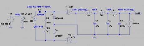
Peek current of AZ1 (in this schematic) about 55mA.
If one half of rectifier is weak, sparking is possible.
Try to increase Rt up to 400R (max. 800R).
Rt= Rsec+n2*Rprim+R1
n2= square of ratio
Rprim: DCR of primary
Rsec= DCR of secondary (if it is CT, the half of secondary)
R1 practically DCR of first L + optional -equal- resistors series with AZ1 anodes.
I found two 47R resistors and soldered them to the secondaries, but it didn't do diddly-squat. I'll try two more in series (as I have several) and see what happens. Perhaps there is no way to "rectify" (pun intended) the rectifier when it has sparked several times already.
Hello all
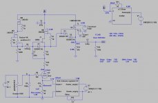
I have been gathering parts for an 01A preamp, which should be similar enough to the 26 to share this thread (for now, at least). I've probably posted about it before, but it's pretty much a direct schematic copy of Ale Moglia's 01A, using his gyrator boards and coleman regulators.
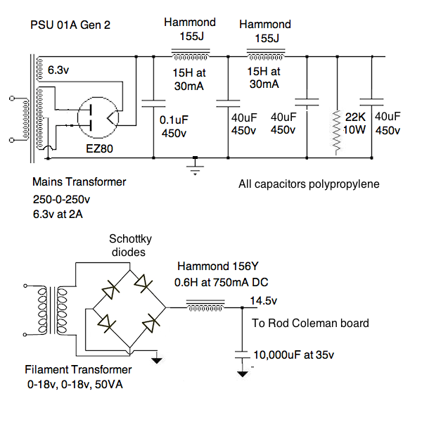
I'm planning on using the attached image to create the B+
power supply, though maybe changing the rectification a bit.
Hopefully this will give about 200V on the B+.
Before I build, there are two things I am wondering about and would like to clear with the DIYAudio community. First, I am having some trouble designing the coleman filament regulators to give me 15V at the output, as all the designs for this voltage seem rated at much higher currents, I'm starving the filaments at 200ma, and using filament bias. I have the raw supply kit, and was planning to use a hammond 266L28 transformer, with two 14V windings, and then on the raw DC supply, to have C1&C2 be 10,000uF, 35V, and have each dropper resistor be a 5W wirewound, and I think I've decided on .5 Ohms. Can somebody who has used these boards chime in with some advice? I've emailed rod, and this is pretty much what I arrived at from his reply.
The second question I have is how I should setup the power. I'm going to have the power supply in a separate chassis, and in past amps, I have applied filament, and then applied B+, but the coleman regulator manual seems to suggest the opposite. What's the proper power-on sequence?
Here's the schematic (Thanks Ale!) for the amp:

I have been gathering parts for an 01A preamp, which should be similar enough to the 26 to share this thread (for now, at least). I've probably posted about it before, but it's pretty much a direct schematic copy of Ale Moglia's 01A, using his gyrator boards and coleman regulators.
I'm planning on using the attached image to create the B+
power supply, though maybe changing the rectification a bit.
Hopefully this will give about 200V on the B+.
Before I build, there are two things I am wondering about and would like to clear with the DIYAudio community. First, I am having some trouble designing the coleman filament regulators to give me 15V at the output, as all the designs for this voltage seem rated at much higher currents, I'm starving the filaments at 200ma, and using filament bias. I have the raw supply kit, and was planning to use a hammond 266L28 transformer, with two 14V windings, and then on the raw DC supply, to have C1&C2 be 10,000uF, 35V, and have each dropper resistor be a 5W wirewound, and I think I've decided on .5 Ohms. Can somebody who has used these boards chime in with some advice? I've emailed rod, and this is pretty much what I arrived at from his reply.
The second question I have is how I should setup the power. I'm going to have the power supply in a separate chassis, and in past amps, I have applied filament, and then applied B+, but the coleman regulator manual seems to suggest the opposite. What's the proper power-on sequence?
Here's the schematic (Thanks Ale!) for the amp:
That's one of my PSUs you have there, and it was indeed meant for Ale's Gyrator, so should work. I should point out that for the gyrator you need some 01A in good condition. I suggest the ST versions which generally work better with the gyrator. I have a number of globe 01As and they don't work at all with the published design of the gyrator - I'm getting 200v on the anode. They may be weaker - I do have a small number of 01A that work, but I do have many that don't. Maybe the values of the gyrator can be changed - I haven't gone into that.
For order of turn-on I turn the filaments on first. For Rod's regs 200mA gives you a large sense resistor value of 4.5R at 1 watt. You should be OK with 4.7R. You design the filament supply to give you the required voltage. With Rod's latest boards you should be OK with 13v which gives you a headroom of 4.5v. 14v would also be OK. Note the 22k resistor to ground which I used with choke input to satisfy critical inductance. This wouldn't be needed with just dropper resistors, but I'd recommend choke input if you can - smoother.
For order of turn-on I turn the filaments on first. For Rod's regs 200mA gives you a large sense resistor value of 4.5R at 1 watt. You should be OK with 4.7R. You design the filament supply to give you the required voltage. With Rod's latest boards you should be OK with 13v which gives you a headroom of 4.5v. 14v would also be OK. Note the 22k resistor to ground which I used with choke input to satisfy critical inductance. This wouldn't be needed with just dropper resistors, but I'd recommend choke input if you can - smoother.
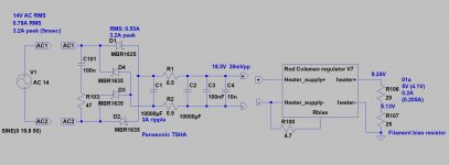
As you can see, 14V AC is enough for filament biased, starved (200mA) 01a.
The raw supply DC voltage is a bit high (higher R.C. dissipation), 5-6V headroom is enough to R.C. regulator.
Instead of 0.5Rs use for example 4.7Rs, so raw supply will be about 16.5V.
In my preamps filament and HV powered at the same time (for a decade). Low power preamp tube usually not sensitive to cold cathode-rising anode voltage problem (few mA anode current).
The situation is different with larger power tubes, my 10/10Y/801/801a tube's filament start first, then HV.
Attachments
Andy, euro21, and Rod,
Thanks so much for the feedback. For the B+ Power supply, would I be good using caps rated at 400V? In PSUDII, the cap spikes at 460V, but only at turn on for about a millisecond, so I'll still use the 450V on that one, but for the other 3, the max seems to be 320V. It's a lot easier and cheaper for me to source caps at 400V.
The other question I have is how to wire in the potentiometer and balance controls. I plan on using 4 Pots total, a coarse and fine pair for the volume, and one for each channel fine adjustment. Essentially, the idea is that I don't want to introduce any unnecessary resistance, and a balance pot would add half of its value at the midpoint. Is this actually something I need to worry about or can I just use a balanced pot? Also, where would I wire it in? I'm thinking at the output, but that leaves the issue about what to do about R8 in the schematic.
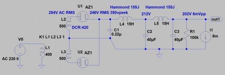
With such high DCR chokes as 155J (1026 Ohm) the 200V output is on the border.
Use higher first capacitor (220nF) and higher bleeder resistor (100k), then output is just over 200V.
Spike on first capacitor???
Empty capacitor (at 0 sec) has virtually zero impedance (only ESR), so its voltage is rising upwards from 0V.
As you can see, the first capacitor peek voltage about 350V so use 450..620V polypropylene.
Attachments
Euro, Thanks so much for all the schematics, I've bought the parts mentioned in post 4568. I've decided to forgo the balance controls for now, and maybe put a small pot on each monoblock amp if necessary.
In terms of the volume pot, I need help deciding where to wire it, and what value pot to use. Across the output seems like it should work, but that brings in the issue of the relatively high gain of the 01A, which might cause clipping on higher voltage sources. I plan on using a stereo blue velvet, and am wondering where I should wire it in.
In terms of the volume pot, I need help deciding where to wire it, and what value pot to use. Across the output seems like it should work, but that brings in the issue of the relatively high gain of the 01A, which might cause clipping on higher voltage sources. I plan on using a stereo blue velvet, and am wondering where I should wire it in.
If you use -relatively large value- potentiometer in the preamp, put in the input side.
Gyrator loaded preamp usually has low output impedance, so driving interconnect and power amp is mostly easy. If you use there volume control (except TVC/AVC), lost of majority of driving capacity.
Gyrator loaded preamp usually has low output impedance, so driving interconnect and power amp is mostly easy. If you use there volume control (except TVC/AVC), lost of majority of driving capacity.
Why?I plan on using 4 Pots total, a coarse and fine pair for the volume, and one for each channel fine adjustment.
IMHO balance is totally unnecessary. Completely uninteresting that sweet spot is in the "middle", or need to sit other position in the sofa.
Coarse and fine tuning separation also wasting of money.
Good (If I use potentiometer, regularly use Noble, TKD or black Alps -RK40- ones) potmeter cost is over 100 dollar.
Matching accuracy 0.2-1dB, attenuation 0...50dB.
If it's a "clicking" version, the steps about 2dB.
Value is indifferent, if you use 22k..200k range.
I don't understand why must use "fine tuning" if the amplifier stages gain is adjustable to equal.

![My[1].jpg](/community/data/attachments/591/591333-40cb990a2e02ceb6b5d0b97c0b2ebaf9.jpg)
the + side of the filament is open...
There are no filament, so + side also missing.
 pp
ppI haven't proper 4 element Spice model for 01a, so use 3 element (anode, grid, cathode) one.
The R12 (10R) represents the half filament, which is need for proper filament bias voltage.
- Home
- Amplifiers
- Tubes / Valves
- #26 pre amp