CCS + shunt.CSS+shunt or shunt+CSS, thats what SSHV is.
 The VR150 (0D3) has a soft purple glow. Also nice.
 Hello guys,
I have some questions if you do not mind.
My raw DC supply out of the filter is 19.4V (same for the other channel). When using umbilical to connect to main preamp, I get 14.4 V at the input of Rod Coleman regs. With the 26 tube and 10 ohm connected (pin 4 is + of the filament regulator, then tube, then pin1 to 10 ohm resistor then negative of the regulator then to 0V system ground), I get 1.15 volts across the filament of the 26 tube(pin 1 and 4), 8.52V across 10 ohm resistor.
At this point, I cannot adjust the filament current anymore using the pot on the board (also true with the other channel). I am wondering why?
I tested the regulators, with the heatsinks of course, and I can adjust the current to about 1.47Amps. Supply is 12 vrms through CLC connected to SUPPLY of RC regulators, then filament reg out connected to a 50W 1.5 ohm resistor.
What could be my problem?
regards,
Abe
Iko,
Thanks! I think I figured it out. I tested the regulators with 18 Vrms(24 Vdc) trafo, not 12 Vrms(14Vdc). With ~4Vdc filament board drop, there is no way I will get 10V to the 10 ohm cathode resistor using the 12Vrms trafo.
Let me change the trafo first to what I have on my PSUD schematic. I don't know why I got the 12V trafo in there and I will report back. And if I do, I will have the schematic and measurements included.
regards,
Abe
Try reversing the leads on the Filament to the 26 Tube...this should clear the Hum...if not try taking out the 2 X 22 ohm resistors and placing a (Humdinger) 100 ohms pot across the filament supply with the middle leg connected to the 2.2K Bias Resistor
I don't follow this at all. You are talking about filament bias here? It's not the same as the "usual" kinds of AC filaments with hum pots.
Yes, Hum pots are only needed for circuits where the filament supply is not quiet enough. With a 26 line amplifier, we always need a very low noise supply, and hum pots will not suffice to solve the problem.
Hum pots are also used for ac heated filaments - but these will sound really bad compared to properly implemented dc, and the noise will be unacceptable.
The best that hum pots can do is to null the 50/60Hz hum components - but little can be done about the 100/120Hz 2nd harmonic generated by the DHT in the presence of filament-current noise.
Felipe is using my Coleman Regulator for the filament supplies - and a hum pot will never be needed with these. If there is a pot present (e.g. from use of a different filament supply) the hum-pot should be removed, for best sound.
Iko,
Thanks! I think I figured it out. I tested the regulators with 18 Vrms(24 Vdc) trafo, not 12 Vrms(14Vdc). With ~4Vdc filament board drop, there is no way I will get 10V to the 10 ohm cathode resistor using the 12Vrms trafo.
Let me change the trafo first to what I have on my PSUD schematic. I don't know why I got the 12V trafo in there and I will report back. And if I do, I will have the schematic and measurements included.
regards,
Abe
I always go through the same routine with filament supplies.
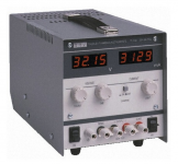
1. On the bench, test the Reg (with heatsinks) connected straight to the two filament pins of a UX4 socket with the 26 in it. I have a bench supply of 30v, 2A (Thurlby Thandar). I gradually increase the voltage up to 5v above the filament voltage - in this case up to 6.5v. I read off the voltage on the filament pins while I'm doing this. I also read out the current on the bench supply, which has a digital readout for volts and current in two separate meters. I wil use a 26 tube that gives me around 1.5v and 1 amp, so I know the tube is in good condition. I then adjust the voltage reg so I get the desired voltage on the filament pins - shall we say 1.5v. I might settle for a starved filament, like 1.4v. I'm now good to go - the filament reg works correctly with an input 5v above the output.
2. I now disconnect one side of the filament wires and place the cathode resistor between the wire from the Reg and the filament pin on the socket. I now have filament bias. I calculate the supply from the Reg that is needed. A 10 ohm resistor at 1 amp gives me 10v bias. Add the 1.5 ohm filaments and we have 11.5v which the Reg needs to supply. So the input to the reg will be 16.5v. I gradually increase the bench supply voltage to 16.5v, measuring the voltage across the filaments of the 26. I'm again aiming for 1.5v. I trim the Reg to get this voltage (or 1.4v etc). This tells me that I'm good to go with a 16.5v supply.
3. I then connect the actual filament supply instead of the Bench supply. The actual supply has to give me something in the range of 16-20v. I will have calculated the size of the transformer needed for this. In my case I use choke input (Hammond 159ZC) so I've factored in the voltage drop for the DC resistance of the choke (0.7 ohms), and I'm assuming the usual calculations for choke input. I connect up the filament supply. I tweak the supply with a small capacitor in front of the choke to get a supply voltage close to what I want - 17-18v will be fine. I'll try caps in the range 100 to 1k ohms, and the voltage will increase with the size of the cap. When I have 17-18v I'm good to go. I then measure the filament voltage and again adjust the Reg so I get 1.5v (or 1.4v etc). I've now finished testing
4. I install the Reg in the preamp chassis. I measure everything again - filament voltage, bias voltage, supply voltage etc. I then leave the supply running for 30m to make sure nothing goes down.
I see numerous posts about problems with implementing filament bias. I strongly urge you to buy and use a good bench supply. A 30v, 2A one is great for this, and it should have two meters - volts and current. You have to constantly measure volts and current when you are building filament supplies for filament bias, and you have to make a number of fine adjustments. Do it all on the bench first and save yourself grief. You must KNOW all the voltages are correct before you install your filament bias supply in your chassis. Follow the correct procedure step by step, be careful at all stages, and measure, measure, measure.
If you use Rod Coleman regs which I and many others recommend, make sure Rod gives you the right resistor values for the filament bias you intend to use. Tell him when you order. The resistor values differ according to the supply voltage you need to provide. He is well aware of all this and gives detailed instructions with his kits. Rod is an uber-professional guy!
I attach a picture of the bench supply type I use. You can use something similar with dual readouts for volts/current. Should be plenty on ebay, new and used. Like I say, 30v at 2A is good for filament bias. I use filament bias for ALL my stages - even the outputs which are parallel 4P1L in PSE. The supply voltage for those is 28v at 1.3A with a 15 ohm cathode resistor. In actual fact, I have a few Thurlby bench supplies and as we speak my PSE 4P1L outputs are running off two 30v 2A supplies into Rod's regs. If you have a couple of bench supplies you can be lazy and use those. They sound great.
Attachments
Last edited:
Hi euro21! Rod will confirm the ideal supply voltage. By 5v I meant not less than 5v voltage drop, but like you say 6v or 7v is good. With a bench supply you can see where the Reg goes into regulation as you increase the voltage, and you then carry on for another 3v or maybe a bit more to get good regulation. I don't know the precise figures but that should be about right.
The 75v glow tubes are pretty spectacular! But for Filipe and for myself as well, I prefer a single tube so you avoid the problems of getting two tubes to strike. Mind, the DN2540 does seem to fire up a couple of tubes pretty well. You can wrap a resistor around the top tube.
The 75v glow tubes are pretty spectacular! But for Filipe and for myself as well, I prefer a single tube so you avoid the problems of getting two tubes to strike. Mind, the DN2540 does seem to fire up a couple of tubes pretty well. You can wrap a resistor around the top tube.
Thanks Andy also thanks for your PM (I sent email to Nic)
26 Hum
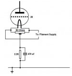
Hi Andy,
Attached is a diagram which may explain it better. Since the Filament is fed with AC...hum can be cured by reversing either the Mains input or the leads feeding the filament. If that does not work then trying something like a 0.22uf from one side of the filament to ground also works. I know I have tried this a number of times
Attachments
- Home
- Amplifiers
- Tubes / Valves
- #26 pre amp