Hi Ale, Yes, it is short of voltage. C2 should have about 10V across it to set a stable current in the P-FET, and The FET needs about 20-30V of Vds, minimum. When the drain-source voltage is too low, the current source shows a lowered dynamic impedance, which makes a bad current source. The LED string needs to increase to at least 25V for good CCS behaviour.
The 6Ж51П circuit looks really good!
Yes, I thought you were going to say that
") You did tell me last time as well when designing the 45 SE driver stage!
You did tell me last time as well when designing the 45 SE driver stage! Perhaps I can try the cascoded MOSFET gyrator instead given that my HT is limited to 200V?
Cheers,
Ale
Hmmm... They went down!
Looks like some military warehouse barn gates had been opened.
Yes, 6Э5П is a very good candidate for cathode follower here.
What is an ideal source impedance to drive the 26? Is it similar to other DHTs where it needs to be quite low? I am trying to plan the summing stage to my mixer, originally I was going to use 6SN7s for the output stage which can take a higher source impedance, but now this thread has taken control of my life I need to plan for using the 26
I really love the free heat idea, im going to look into using such valves in the design. It would be also be great to not have so much heat in the unit when there won't be much space around.
... Still playing with ideas, thanks for you help
Charlie
I really love the free heat idea, im going to look into using such valves in the design. It would be also be great to not have so much heat in the unit when there won't be much space around.
... Still playing with ideas, thanks for you help
Charlie
Just a quick update:
Over the weekend I wired up my preamp without the 26 circuitry; basically making a passive preamp to test that all of my autoformer wiring was correct. I had one mistake (forgot to reference the secondary to ground). This got me thinking....
Im using Kevin's design, which uses a .1uF input cap. Being that Im using an autoformer - do I really need this input cap ? I would assume it is in place to block DC from the previous stage...
Thanks !
EDIT - on second look - doesn't seem like it will work with the schematic as-is. I'll be starting off with Grid Bias, so with the secondary grounded it'll short out the bias circuit.
Last edited:
Question, if using filament bias on a c-LC-RC-L filament supply that can reduce ripple to 2mV using two 25mH DC filament chokes. Is a 25mH choke sufficient as the second L to isolate the filament supply from the signal, since the "LCL" configuration has been promoted?
25mH is only about 16 ohms, even at 100Hz - so it would be some way short. It's usually worth checking the leakage capacitance of these, too - to see that there is some HF noise blocking.
What is an ideal source impedance to drive the 26? Is it similar to other DHTs where it needs to be quite low? I am trying to plan the summing stage to my mixer, originally I was going to use 6SN7s for the output stage which can take a higher source impedance, but now this thread has taken control of my life I need to plan for using the 26
I really love the free heat idea, im going to look into using such valves in the design. It would be also be great to not have so much heat in the unit when there won't be much space around.
... Still playing with ideas, thanks for you help
Charlie
It's not quite the brute that a 300B is - where the grid resistor is only 50K for fixed bias, and the Cin is up to 100pF.
The corresponding values are usually 220K and about 40pF for the 26, and the grid drive voltage is usually below 5V peak.
For those conditions, the drive current is about 70uA peak for 5V peak, even at 50kHz.
This is a lot easier than a 10 or 20K pot, as may be seen on many power amps. You should be able to drive the 26 with almost any kind of valve or solid state source - well, a ECC83/12AX7 stage might be pushing it.... but please remember to calculate the cable current, as well - if you are running any.
Hi!
The 26 does not require a low source impedance to be driven. It is very easy to drive. Not much different from a 6SN7
Best regards
Thomas
What is an ideal source impedance to drive the 26? Is it similar to other DHTs where it needs to be quite low?
The 26 does not require a low source impedance to be driven. It is very easy to drive. Not much different from a 6SN7
Best regards
Thomas
Hi!
I agree with Rod that 25mHy would be too low. I'm using Ls in the range of several 100mHy. Lundahls LL2733 can be gapped for 1A and yields 700mH like this.
Also 2mV ripple on the filament of a DHT in a linestage is quite high. This will be amplified by the 26.
If you want to use LCL, use some serious inductance. If budget or space does not allow for bigger coils, I'd rather use Rod's regulator
Best regards
Thomas
Question, if using filament bias on a c-LC-RC-L filament supply that can reduce ripple to 2mV using two 25mH DC filament chokes. Is a 25mH choke sufficient as the second L to isolate the filament supply from the signal, since the "LCL" configuration has been promoted?
I agree with Rod that 25mHy would be too low. I'm using Ls in the range of several 100mHy. Lundahls LL2733 can be gapped for 1A and yields 700mH like this.
Also 2mV ripple on the filament of a DHT in a linestage is quite high. This will be amplified by the 26.
If you want to use LCL, use some serious inductance. If budget or space does not allow for bigger coils, I'd rather use Rod's regulator
Best regards
Thomas
Computer Audio Asylum
I came across this power supply from John Swensen who has recommended snubbers of 22nF and 330 ohms in his experiments. It uses a choke in the PSU - something like I've been using and as Thomas recommends. The supply is low power but could be scaled up. Chokes can be simple Hammonds - for the 26 filament supply the model is 159ZC, 60mH 2A. There is a 159ZA, 300mH 1A. A bit close for a 26, but maybe OK in starved filament. This might precede a Rod Coleman board - I don't know how much Rod would find this necessary. I use choke input with a small cap just like this circuit for filament bias. I don't use the LM1084 which may be redundant here with Rod's supply.
I came across this power supply from John Swensen who has recommended snubbers of 22nF and 330 ohms in his experiments. It uses a choke in the PSU - something like I've been using and as Thomas recommends. The supply is low power but could be scaled up. Chokes can be simple Hammonds - for the 26 filament supply the model is 159ZC, 60mH 2A. There is a 159ZA, 300mH 1A. A bit close for a 26, but maybe OK in starved filament. This might precede a Rod Coleman board - I don't know how much Rod would find this necessary. I use choke input with a small cap just like this circuit for filament bias. I don't use the LM1084 which may be redundant here with Rod's supply.
Attachments
Last edited:
Yes, the snubber is recommended. The details are in my application note, where 47R & 100nF are stated - but the values are not critical.
The purpose is to introduce electrical damping to the tuned circuit formed by the (leakage) inductance of the transformer, and the total of stray capacitances around the transformer-rectifier loop.
For perfection, you can make a little current-probe (toroidal core made from inductor-type ferrite, with a few turns). Slide the toroid over a wire in the rectifier circuit & scope the turns on the probe, and adjust the R and C to obtain the smallest & smoothest turn-OFF pulse.
But just using the suggested values should be good enough for almost all designs.
So I've begun work on the 26 preamp, and am building the first version on a plywood board so that I can tweak to my heart's content before making a nice chassis.
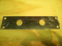
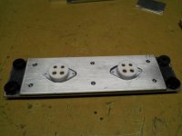
I'm isolating the 26 tube on a sub-assembly in order to control microphonics. I've attached a few pictures of how I've assembled this in case you're curious. It starts with a 4mm aluminum plate (courtesy of andyjevans' fire sale a few weeks ago), into which I've drilled and punched the appropriate holes for the sockets and mounting bushings (picture 1).
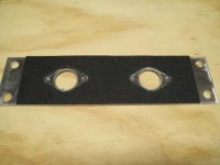
To this is added a layer of self-adhesive Soundcoat absorbent material (sheets purchased from Parts Connexion) - picture 2.
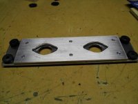
On top of that goes another 4mm aluminum plate, which is glued and bolted down. (picture 3)
Connex teflon tube sockets (economy grade) from PCX are added - picture 4. The Connex economy teflon sockets are perfect here as they provide some damping of their own and because the body of the socket is quite long, allowing the socket to stick up through the outer chassis which will eventually be added over the mounting plate.
The mounting is through Deflex bushings on each corner; I made them from Deflex vibration absorbing washers (also PCX) by sandwiching a cored out center of one Deflex washer between two full size Deflex washers.
The assembly is very dead sonically, rapping on it produced a soft thunk, as opposed to the ringing of the plain aluminum plate.
Overkill? Perhaps, but I think I can be confident that I've dealt with chassis-borne vibrations, anyway...
I'm isolating the 26 tube on a sub-assembly in order to control microphonics. I've attached a few pictures of how I've assembled this in case you're curious. It starts with a 4mm aluminum plate (courtesy of andyjevans' fire sale a few weeks ago), into which I've drilled and punched the appropriate holes for the sockets and mounting bushings (picture 1).
To this is added a layer of self-adhesive Soundcoat absorbent material (sheets purchased from Parts Connexion) - picture 2.
On top of that goes another 4mm aluminum plate, which is glued and bolted down. (picture 3)
Connex teflon tube sockets (economy grade) from PCX are added - picture 4. The Connex economy teflon sockets are perfect here as they provide some damping of their own and because the body of the socket is quite long, allowing the socket to stick up through the outer chassis which will eventually be added over the mounting plate.
The mounting is through Deflex bushings on each corner; I made them from Deflex vibration absorbing washers (also PCX) by sandwiching a cored out center of one Deflex washer between two full size Deflex washers.
The assembly is very dead sonically, rapping on it produced a soft thunk, as opposed to the ringing of the plain aluminum plate.
Overkill? Perhaps, but I think I can be confident that I've dealt with chassis-borne vibrations, anyway...
Attachments
Last edited:
Looking neat and clever!
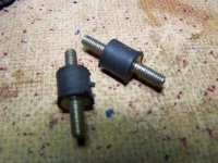
I got good results using these stand-offs.. It is soft natural rubber in between two threaded rods.. They are supposed for vibration damping.. These are M4 but also available for M3 and with one threaded rod and nut/insert.
When used, you can move the valve almost 45 degrees to each side and tapping on the chassis is barely heard through my speakers (only a very soft thunk).
These allow me even to use a stepped attenuator...
Rob
I got good results using these stand-offs.. It is soft natural rubber in between two threaded rods.. They are supposed for vibration damping..
These are M4 but also available for M3 and with one threaded rod and nut/insert.When used, you can move the valve almost 45 degrees to each side and tapping on the chassis is barely heard through my speakers (only a very soft thunk).
These allow me even to use a stepped attenuator...
Rob
Attachments
Where do you buy them Rob?I got good results using these stand-offs..
Hi Bas,
Here: Verpas - Groothandel in doppen en kunststofproducten
Lots of different sizes etc etc..
Rob
Here: Verpas - Groothandel in doppen en kunststofproducten
Lots of different sizes etc etc..
Rob
Hi!
Although the Lundahl LL1660 works very well with the 26, a transformer with a higher step down ratio would be better for the 26 if a output impedance is needed to drive real 600 Ohm loads like a LCR RIAA EQ. For that a ratio closer to 6:1 would be better. I convinced Lundahl to add such a transformer to his line up. See my blog post about it:
VinylSavor: New Lundahl Line Output / Interstage Transformer
I will build a 26 preamp around this transformer soon
Best regards
Thomas
- Home
- Amplifiers
- Tubes / Valves
- #26 pre amp