These were the best sounding resistor types for me
Even better than the Welwyn wire wound you indicated in post 1117?
I recall someone mentioning that the old stock green Welwyn vitreous enamelled ww were pretty good. Have you tried these?
Rich
Even better than the Welwyn wire wound you indicated in post 1117?
I recall someone mentioning that the old stock green Welwyn vitreous enamelled ww were pretty good. Have you tried these?
Rich
Those dark green Welwyn resistors are fine. I never used them for filament bias because here we need about 50 watts. But anyway, the discontinued Dale ones are really good so I'd go for those. They are surplus supplies, so may be worth buying some. Don't know what remaining stock there is.
Andy
I have a question about the LL1660/5mA as preamp output. I've put this back in the circuit. A bit light on bass but transparent and clean sound. It's in 1:1 but may try 4.5:1 if I have enough gain.
Anyway, the question is what current can be put through this while allowing it to remain totally undistorted whatever the programme material. I have a feeling it's less than 5mA. Any comments on this?
Andy
Anyway, the question is what current can be put through this while allowing it to remain totally undistorted whatever the programme material. I have a feeling it's less than 5mA. Any comments on this?
Andy
I have a question about the LL1660/5mA as preamp output. I've put this back in the circuit. A bit light on bass but transparent and clean sound. It's in 1:1 but may try 4.5:1 if I have enough gain.
Anyway, the question is what current can be put through this while allowing it to remain totally undistorted whatever the programme material. I have a feeling it's less than 5mA. Any comments on this?
Andy
Try it and find out I guess. The HA-133s in mine are rated 8mA and sound bad at this current and wonderful at 6mA..
I'd recommend using it at 4.5:1 as this will give you a very low source impedance for driving lines effectively and should give you about 4.5dB of gain. I find the 4dB of gain in mine more than adequate.. (5:1)
Hello Kevin! I was thinking along these lines that about 3/4 current would sound cleaner. That would make about 3.5 to 3.7mA. Listening to some choral music at the moment, which caused me to wonder - it can be tricky to get choral music to sound completely clean.
My whole system is CD player > 26 > 46 > 300b. All transformer coupled, no resistor loading or cathode resistors (except 300b). Filament bias on the 26 and battery grid bias on the 46. I have a little gain in hand but am about to switch to Jordan JX92 units, and those may swallow the gain.
Andy
My whole system is CD player > 26 > 46 > 300b. All transformer coupled, no resistor loading or cathode resistors (except 300b). Filament bias on the 26 and battery grid bias on the 46. I have a little gain in hand but am about to switch to Jordan JX92 units, and those may swallow the gain.
Andy
Hi Andy,
when you talk about 'light bass' do you mean it has an early roll off? What is the -3dB frequency? What is the general behaviour in the bass, what was it in the circuit you compared it too?
How did you wire it? The 1660 does not offer exactly 1:1 did you put it 1:1.125 or 1.125:1 ? Worth trying if slight step up is better than slight step down.
The current depends on the signal swing you need. If you increase the current, you get less possible signal swing before saturation kicks in. Again this can be easily measured. When you change current the rp of the driver will change. So you will compare several effects. It might not be the impact of the current to the transformer you are hearing, but the different rp in conjunction with the transformer.
Also impostant, how is the B+ of this stage done? If it has it's own decoupling stage, the size of the decouplig cap also palys a role.
Best regards
Thomas
Hi Thomas -
I don't use a scope alas - never learned. Just sounds like less bass than with the two Hammond 156c plate chokes - they take 8mA. Wiring - good point. I should at least make it 1.25:1. I'll look what I did. The Rp difference wouldn't make the sound congested, though. I've been looking again at the curves and I need 120v on the anode not 130v at present. Will swap that for starters. The B+ is decoupled with a 6.3K resistor and a 47uF cap. There are two chokes in the HT, which is choke input. I never did try ultrapath - run that by me again!
Comments?
andy
Hi Andy,
I recommend to do basic measurment checks when you try a new circuit, otherwise it is diffcult to understand what is going on and you easily draw false conclusions. A scope and signal gen are easy to use and you will learn a lot by using them.
Changing the B+ by 10V shouldn't make a big difference. If it does the circuit is marginal and I would rather make the whole circuit more stable rather than trying to find the optimum voltage.
Also note that your last B+ cap now is fully in the signal path while with LC coupling it was not.
Ultrapath is adding a cap from B+ to cathode. Many schematic on my blog show this. Does not make a huge difference with filament bias, but you could still try
Best regards
Thomas
Hi - well, 10v difference on the anode means a difference between 3.5mA and 4.8mA. There isn't much of a margin with the LL1660/5mA. It's all very tight through the need to keep the Henries up for the 26. A LL1660/10mA would give a nice margin but then we lose the impedance headroom.
Why is there a difference between transformer output and a plate choke and cap output? I don't quite see this in terms of the last B+ cap being in the signal path - do explain!!
Andy
Why is there a difference between transformer output and a plate choke and cap output? I don't quite see this in terms of the last B+ cap being in the signal path - do explain!!
Andy
Hi Andy,
ah, I forgot, filament bias, so you adjust your current through B+. Still I would not feel comfortable if that change would have a significant sonic impact. As the circuit and tubes age things move and would then change the sound too.
How did you get these current values? Did you measure them or just read them from the datasheet? Keep in mind that actual tube samples can differ quite significantly from the nominal values. Even if they are NOS. You can have a spread from 60 to 110% ! Again a reason why the circuit should be tolerant to such variations.
It is a common misconception that transformer coupled circuits have no cap in the signal path. The signal travels in loops. Each stage has a input and output signal loop. The output loop is in case of transformer coupling: tube plate to transformer primary to B+ from there through the last B+ cap to ground from ground through the cathode resistor anf bypass cap (if any) to the cathode and through the tube to the plate.
This is where ultrapath comes into play. The ultrapath cap 'shortens' the signal path from B+ directly to the cathode. There is a similar idea behind filament bias, the cathode resistor is of smaller value which has less sonic impact (IME) and which does not need a bypass cap.
With LC coupling the plate choke efectivly decouples the B+ from the signal path since it is a high AC impedance. The signal travels from the plate through the coupling cap to the grid of the following stage. From here through the grid resistor to ground and back to the cathode through the cathode resistor and bypass cap.
This is an idealized way of looking at the signal path. In reality there will be a multitude of parallel paths due to stray capacitances, leakage inductances and what not. Still looking at it this way helps to understand which parts are important. In your case the sound will be mainly influenced by the tube, transformer and that 47uF cap. This cap should be of best quality. An electrolytic here can ruin the whole thing. Also note that a cap which works well as coupling cap, might not sound as good as last B+ cap.
This is why I remind people to be cautious to jump to conclusions how a certian part sounds. It is always all those parts in the signal path which act together.
Don't get too hung up about the current through the transformer. You do not use the full signal swing it can deliver, which gives more current headroom.
Still I would encourage you to start to do some basic measurements to make sure everything is where it should be. Sure the ear should be the final judge, but the basic technical parameters need to be in order to ensure the listening test is meaningful.
Best regards
Thomas
Hi again,
one more remark: keep in mind that depending if you have the filament resistor connected to the + or - side of the filament, half of the filament voltage will be either added or subtracted from the bias voltage.
With filament bias or fixed bias, plate current can be easily measured by getting the voltage drop through the transformer primary winding. Then calculate the current by ohms law from that voltage and the DCR of the winding. Also if you use RC decoupling in the B+ you can do the same by measuring the voltage across the dropping resistor.
Thomas
Hi Thomas,
Don't worry, I measure extensively to determine operating points, current, voltages, resistances etc. I have a huge set of equations I've put into Excel spreadsheets. I calculate everything even though I don't use a scope.
I had in fact read the operating point off the curves in the first instance. The true current going through the 26 is between 3 and 3.5mA depending which valve. That's actually fine and does not need changing.
Next to look at which way round I have the LL1660 - this turns out to be 4:4.5. Now, what I don't know is how many Henries I would have on the "secondary" of 4.5 (1.25K static resistance) as opposed to the "primary" of 4 (1.1K). If I get as many Henries (or more) on the 4.5 side I can also try this in 4.5:2 (alt T).
Do you have any idea of these impedances in Henries?
Andy
Hi Andy,
the inductance scales by the square of the windings. So the factor is (4.5/4)*(4.5/4) which is about 1.26
So the other way around is .79. That's more of a difference than I thought. Must try it in 4.5:4.
I take your point about the current. Some experiments coming!!
Andy
Hi guys,
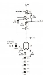
I have been playing around with a test bed for a 26 pre-amplifier. What I also did was to measure various valve distortion on a simple setup. Mine is a CCS loaded 26 valve with LED bias for simplicity, and also what I had at hand.
My laptop/soundcard is having some issues in measuring distortion, however I had applied same method across the board, so what I aimed at in my tests was to identify which valve/brand had the lowest distortion figure.
I run the 26 at 8mA and anode voltage was around 145V to 160V depending on the valve. In summary what I found was that lowest distortion was provided by the Sylvania ST 26s. See below my table:
The LED array provided Vg=-8.2V @ 8mA
Valve THD
Sylvania 26 ST 0.022%
National Union ST 0.0305%
CX326 globle 0.046%
Super Silvertone ST 0.046%
Sylvania 26 globe 0.024%
I did get slightly better results with the 4P1L! This valves is really linear. Well, Andy said it's very microphonic. So will need to do a listening test.
I will build a modular pre-amp so I can play around and exchange different valve types, loads like choke, CCS, etc. and different bias
Hope you find this simple testing a bit interesting as I did!
Cheers,
Ale
Attachments
Check my calculations here to see if they are correct (I've simplified a bit):
Voltage into 26 = 2v
Mu = 8
Ra = 8
Voltage out of 26, into LL1660 = 16v
Voltages out of LL1660:
4:4.5 = 18
4.5:4 = 14
4.5:2 = 7
4.5:1 = 3.6
If this is correct, I personally would need 4:4.5 or 4.5:4 for my 3 amplification stages (followed by 46 and 300b). I can try 4.5:2 but it looks a bit short.
Andy
Hi guys,
I have been playing around with a test bed for a 26 pre-amplifier. What I also did was to measure various valve distortion on a simple setup. Mine is a CCS loaded 26 valve with LED bias for simplicity, and also what I had at hand.
My laptop/soundcard is having some issues in measuring distortion, however I had applied same method across the board, so what I aimed at in my tests was to identify which valve/brand had the lowest distortion figure.
I run the 26 at 8mA and anode voltage was around 145V to 160V depending on the valve. In summary what I found was that lowest distortion was provided by the Sylvania ST 26s. See below my table:
The LED array provided Vg=-8.2V @ 8mA
Valve THD
Sylvania 26 ST 0.022%
National Union ST 0.0305%
CX326 globle 0.046%
Super Silvertone ST 0.046%
Sylvania 26 globe 0.024%
I did get slightly better results with the 4P1L! This valves is really linear. Well, Andy said it's very microphonic. So will need to do a listening test.
I will build a modular pre-amp so I can play around and exchange different valve types, loads like choke, CCS, etc. and different bias
Hope you find this simple testing a bit interesting as I did!
Cheers,
Ale
Those #'s are very good, this was on the mu out? What was the load? Most soundcard have a terrible load for testing preamps (~1k).
Hi Andy,
Yes they are correct except that the mu of the 26 is 8.3 but that doesn't make a big difference. Also the numbers are only correct if the transformer secondary is unloaded
Thomas
Check my calculations here to see if they are correct (I've simplified a bit):
Yes they are correct except that the mu of the 26 is 8.3 but that doesn't make a big difference. Also the numbers are only correct if the transformer secondary is unloaded
Thomas
- Home
- Amplifiers
- Tubes / Valves
- #26 pre amp