Just to add, the 8 way speakon is more expensive and rather big. I actually use it for the filaments of driver and output tubes in my amp, so the filaments can't be connected to the wrong supply - the 4 pole XLR is for the input stage. For the HT to my amp I use an Amphenol AP-4-22 connector - cheap and rated for 650v.
Andy
Andy
I only see 2 x 3.75VAC 2A.can be enoug with one tx?
Erwin, what's the current rating on the chokes? This will tell you whether shared chokes between L & R channel is possible or not.
Choke-input constructed B+ is definitely recommended.
Well Quasi-choke input anyway. So CLCLC, but with first cap only 0.47uF to 1.5uF (high quality polypropylene, NOT motor-run plastic-housed type). The LCR components PC/HV/S is my favourite in this position.
LCR COMPONENTS|PC/HV/S/WF 470NF 1KV|CAPACITOR, 470NF, 1000V | Farnell United Kingdom
First L should be the 10H (provided this has the highest current rating, preferably 20 - 30mA.
With 20H in the second choke position (rated 10mA+ I hope!) you can used high quality capacitors, without high values.
Hi Rod,
I don't understand why the first cap should have such a low value. Is this to protect the rectifier tube?
With the PT I have, a choke input would drop the B+ voltage too far. I was assuming 40uF / choke / 40 / choke / 40 plus various bypass caps. How would I integrate a 0.47uF into that? Does the ground lug of the small-value cap still function as the star ground for high-current stuff?
Last edited:
Hi Rod,
I don't understand why the first cap should have such a low value. Is this to protect the rectifier tube?
With the PT I have, a choke input would drop the B+ voltage too far. I was assuming 40uF / choke / 40 / choke / 40 plus various bypass caps. How would I integrate a 0.47uF into that? Does the ground lug of the small-value cap still function as the star ground for high-current stuff?
Hi, The reason for choosing choke-input is that the rectifier conducts for a longer part of the mains waveform.
This is kinder to the rectifiers, regulates better, and reduces electromagnetic emissions.
It is relative though, so if you need to have cap-input, just use a 40uF in place of the 0.47uF.
You can t"Tune" the output voltage of a CLC filter by adjusting the value of the first cap.
The lower the value of the first cap, the higher the output voltage and the more efficient the system becomes as the inductor actually stores energy temporarly and returns it to the system.
The lower the value of the first cap, the higher the output voltage and the more efficient the system becomes as the inductor actually stores energy temporarly and returns it to the system.
You can t"Tune" the output voltage of a CLC filter by adjusting the value of the first cap.
The lower the value of the first cap, the higher the output voltage and the more efficient the system becomes as the inductor actually stores energy temporarly and returns it to the system.
I thought the lower the value of the first cap, the lower the output voltage since you are going towards choke input which is near 1:1 rather than 1:1.4 with cap input. Am I not seeing something here?
Andy
I thought the lower the value of the first cap, the lower the output voltage....
 it goes without saying.....
You can t"Tune" the output voltage of a CLC filter by adjusting the value of the first cap.
The lower the value of the first cap, the higher the output voltage and the more efficient the system becomes as the inductor actually stores energy temporarly and returns it to the system.
I think they were discussing choke input filters with a small input capacitor to tweak the output voltage. In any event the inductor is storing energy in its magnetic field whenever load current flows. From direct experience this works and it is possible to adjust the output voltage over a range of about 0.9 to 1.4 times the rms value (not that I would over that range) depending on the capacitor used - but only with a supply intended to operate as a choke input. Note the above comments are predicated on the fact that the load current is above the inductor's critical current for regulation if not it behaves like a standard CLC filter.
Some old timers actually considered it to be bad form to use an input cap to trim the output voltage on a choke input filter.

Last edited:
Ley de Ohm: Ley de Ohm - Wikipedia, la enciclopedia libre
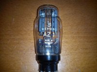
The AZ1 has a 4 V filament rated at 1.1 A
6.3 - 4 = 2.3 Vdrop
R = V/I thus R = 2.3/1.1 then R = 2.09 Ohm
The resistor should dissipate P = I2 x R thus 1.21 x 2.09 then P = 2.53 W
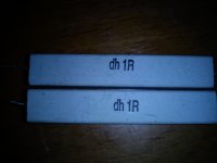
I would use 2-2.2 Ohm/10 W minimum, or, better, split the resistor and use 2 x 1-1.1 Ohm/5 W, one resistor on each cathode.
Quite easy
Edit: http://www.stud.feec.vutbr.cz/~xvapen02/vypocty/ohm_zak.php
The AZ1 has a 4 V filament rated at 1.1 A
6.3 - 4 = 2.3 Vdrop
R = V/I thus R = 2.3/1.1 then R = 2.09 Ohm
The resistor should dissipate P = I2 x R thus 1.21 x 2.09 then P = 2.53 W
I would use 2-2.2 Ohm/10 W minimum, or, better, split the resistor and use 2 x 1-1.1 Ohm/5 W, one resistor on each cathode.
Quite easy
Edit: http://www.stud.feec.vutbr.cz/~xvapen02/vypocty/ohm_zak.php
Last edited:
- Home
- Amplifiers
- Tubes / Valves
- #26 pre amp