This is not good. I think OD3 for shunt, the sound is not good!
OK we hear you.
 But you are being absolute now.
What is bad? A CCS and a couple of OB3s? Naahh. Sounds silky. Its just lacks resolution and impact but not bad. Have you used that circuit, CCS and tube ''zeners'' exactly?
isn't the problem with regulator tubes is it makes the PS have a high output impedance?
This is not good. I think OD3 for shunt, the sound is not good!
OK guys. I am planning to try Salas PSU with in next few days. Then I could give a fair comparison I guess.
isn't the problem with regulator tubes is it makes the PS have a high output impedance?
OK guys. I am planning to try Salas PSU with in next few days. Then I could give a fair comparison I guess.
Guys I don't know so many applications of the SSHV on DHTs. The classic road is OD, a ballast resistor or tube CCS, heavily a depletion Mosfet CCS for the super modernist.
Cygnus X1 said some words on DHT and the SSHV once.
http://www.diyaudio.com/forums/tube...hing-other-than-dhts-preamps.html#post1741756
Don't know, prove him right or wrong, by DIYing one and testing. Its a nice hobby.
Your guess is right. I tried it without the dropping resistor but CCS couldn't handle the flow. This way it works. As long as I keep the dropping resistor in place, nothing much of heat generated in CCS. Tested it for couple of hours and it was quite OK with running both the channels together. Current through the tube is close to 6ma. CCS is with a 3W heat sink btw. If my memory is correct, K&K's suggestion was to use the CCS after the VR's initially. I tried both the ways and felt there is slightly more resolution to the sound with latter. What do you think?
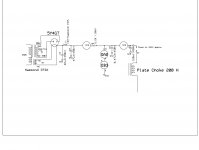
Sorry, it was a mistake mentioning both VR tube as OB3. Actually the first tube I am using is an OA2. Voltage is around 240 volts on plate chokes.
Since you are in the experimental mode, why not try a choke input supply? Just eliminate C3. That will lower the voltage to the CCS to something around 270V. Then you can eliminate the dropping resistor. This applies whether using the VR tubes or Salas's regulator.
Sheldon
isn't the problem with regulator tubes is it makes the PS have a high output impedance?
High compared to what, and applied how? In this circuit, the supply is feeding a plate choke, which is a sort of CCS. The impact of the preceding impedance will be less than it would be for a resistor loaded circuit. Better, worse? Preferred sound is a subjective thing. If technical performance (impedance, distortion) were the only issue, we wouldn't bother with tubes.
Sheldon
edit: BTW, I'm with Salas here. It's DIY. So TIY (Try It Yourself).
Last edited:
Guys I don't know so many applications of the SSHV on DHTs. The classic road is OD, a ballast resistor or tube CCS, heavily a depletion Mosfet CCS for the super modernist.
Cygnus X1 said some words on DHT and the SSHV once.
http://www.diyaudio.com/forums/tube...hing-other-than-dhts-preamps.html#post1741756
Don't know, prove him right or wrong, by DIYing one and testing. Its a nice hobby.
Salas,
I agree with Cygnus X1 about your SSHV; it is certainly one of the best PSU's I have tested with my 26 so far. Easy to build and spot on with results. I couldn't agree more with Cygnus X1 about the things he mentioned of this PSU; it makes 26 pre sounds more musically accurate for sure. It is dead silent too. Anyone who wants to build a 26 pre without putting much of sweat to do R&D for a better B+ supply, this is a clear winner. Only drawback is to have bigger heat sinks. When compared to the results this issue is negligible I would say. A Big thank to Salas to put his effort to design this.
On the other note, I did few more trial and error kind of testing with my B+ supply, without thinking much about engineering behind it. I just placed 2 K&K CCS's (DN2540/IXTP01N100D) before and after the VR tubes in my current PSU (image attached). This gave me totally an unexpected result. Sound became more focus, accurate and well imaged. B+ became totally silent too. If someone is bit lazy to build Salas, this I would say the next best alternate. Don't ask me why I have done this and I didn’t bother to understand the theory behind. I was too tired and just wanted to enjoy the sound: D
Attachments
Last edited:
About your comments and thanks you are welcome. Try it with an IRF9610 in SSHV's CCS too if you didn't already. Its a an alternative to taste. Was it the Simpler Simplistic with Jfet in the Norton Vref? Heatsink can be minimum possible if just 25mA is reserved over max draw, and just 15Vin-VOut is fixed. Any picture by the way?
For your second experiment, the right hand part fixed the current through the anode load. You effectively put sand in your anode loop!
For your second experiment, the right hand part fixed the current through the anode load. You effectively put sand in your anode loop!
Either add some series resistance to the gas tubes, or decrease the 0.47uF cap in parallel with them. You are inviting oscillations with that large a cap.
There is a 10R in series already whcih I forgot to metnion in the image. should it be enough though?
About your comments and thanks you are welcome. Try it with an IRF9610 in SSHV's CCS too if you didn't already. Its a an alternative to taste. Was it the Simpler Simplistic with Jfet in the Norton Vref? Heatsink can be minimum possible if just 25mA is reserved over max draw, and just 15Vin-VOut is fixed. Any picture by the way?
For your second experiment, the right hand part fixed the current through the anode load. You effectively put sand in your anode loop!
Salas,
For the moment, I removed the SSHV from my pre of lacking a proper heat sink and space in the enclosure. Probably I can put a pictures as soon as I fix it back. Used the quanghao's printed board diagram he published in some other thread and used the same schematic. BTW I messed it up a bit when hand drawing the board
. Because currently I’m in Dubai, couldn’t get the board screen printed. PPl here taking too long and too much money for this type of work . However, I couldn't find the SK170 instead I tried it with SK43. It worked but not sure whether it is a suitable alternative. Any suggestion you could give instead of SK170? Everything else is exactly the same as your schematic. I will try 9610 and let you how it goes.BTW, can you explain little more of what you have meant by "keeping 25mA is reserved over max draw, and just 15Vin-VOut is fixed"? Is there any suggested way of doing this? Sorry I have a very little knowledge about electronics.
2SK117 is an alternative but 170 is preferable for a bit better noise.
About current I meant that after you know your max current draw from load, calculate and set the CCS for 25mA more. That residual keeps the shunt Mosfet low impedance enough. So don't go set arbitrary too much and get unwanted heat. What is the bias current of your 26, and what is the Vin-Vout difference you used for the reg? Set the total current at 150% bias + 25mA and keep Vin-Vout (DCin to reg - B+) low, but not lower than 15V.
About current I meant that after you know your max current draw from load, calculate and set the CCS for 25mA more. That residual keeps the shunt Mosfet low impedance enough. So don't go set arbitrary too much and get unwanted heat. What is the bias current of your 26, and what is the Vin-Vout difference you used for the reg? Set the total current at 150% bias + 25mA and keep Vin-Vout (DCin to reg - B+) low, but not lower than 15V.
There is a 10R in series already whcih I forgot to metnion in the image. should it be enough though?
I doubt it. Given the actual design topology, there is very little use for a cap in that location. Better to reduce it to 0.068uF or less. Keep the 10R for measuring shunt current.
2SK117 is an alternative but 170 is preferable for a bit better noise.
About current I meant that after you know your max current draw from load, calculate and set the CCS for 25mA more. That residual keeps the shunt Mosfet low impedance enough. So don't go set arbitrary too much and get unwanted heat. What is the bias current of your 26, and what is the Vin-Vout difference you used for the reg? Set the total current at 150% bias + 25mA and keep Vin-Vout (DCin to reg - B+) low, but not lower than 15V.
I doubt it. Given the actual design topology, there is very little use for a cap in that location. Better to reduce it to 0.068uF or less. Keep the 10R for measuring shunt current.
Thanks Salas/Zigzag.
Salas,
One small question.Does it degrade the SSHV performance by using high series resistance before the SSHV to drop the voltage/current? I have a trafo putting around 370V/80ma after rectification and CLC. Need to get 240V/8ma through SSHV but with minimal heat dissipation. Any easy method you could suggest?
One small question.Does it degrade the SSHV performance by using high series resistance before the SSHV to drop the voltage/current? I have a trafo putting around 370V/80ma after rectification and CLC. Need to get 240V/8ma through SSHV but with minimal heat dissipation. Any easy method you could suggest?
The resistance is a pre filter if feeding a cap, not bad, but put it right after the rectifier before first cap. Set for 35mA CCS and 255-260V DCin to reg. Truth is that the damping isn't as good as having the right trafo and just CLC. That leads me to think that if you just make it choke input by losing the first cap, maybe you get enough voltage sag without resorting to additional RC?
The resistance is a pre filter if feeding a cap, not bad, but put it right after the rectifier before first cap. Set for 35mA CCS and 255-260V DCin to reg. Truth is that the damping isn't as good as having the right trafo and just CLC. That leads me to think that if you just make it choke input by losing the first cap, maybe you get enough voltage sag without resorting to additional RC?
Thanks Salas. Sheldon suggested the same. It will be around 270V for DCin then. I found the thread that you explained of setting ICCS. I will try with 35ma set on CCS and see how it goes. BTW, assuming if I managed to operate within those limits, what type of sink you could recommend? 3.7ºC/W (1.65 _ 1.00 _ 1.50) would be enough? (Rth = (100°C-40°C)/11W). Hope my calculation is correct.
Idle dissipation will be 6.5W for the shunt element and 1W for the CCS element with your setting. Get a 2.5C/W for both to mount. UAE is fully air con, where is the environment set? 22C? Best is not to measure over 50C on the fins. Don't forget IRF9610 to test too, since it will be only 1W on it. Maybe you can use an LM317 light style sink on it as it is TO-220 and use the 3.7W/C only for the IRF840 if you prefer separate, but one of those two in the links maybe elegant on a chassis?. You know, flat upon top with the Mosfets hidden under, or mounted vertically extending the back face.
FISCHER ELEKTRONIK|SK 100/50 SA|HEAT SINK, 50MM, 2.5°C/W | Farnell United Kingdom
FISCHER ELEKTRONIK|SK 81/ 75 SA|HEAT SINK, EXTRUDED | Farnell United Kingdom
FISCHER ELEKTRONIK|SK 100/50 SA|HEAT SINK, 50MM, 2.5°C/W | Farnell United Kingdom
FISCHER ELEKTRONIK|SK 81/ 75 SA|HEAT SINK, EXTRUDED | Farnell United Kingdom
Idle dissipation will be 6.5W for the shunt element and 1W for the CCS element with your setting. Get a 2.5C/W for both to mount. UAE is fully air con, where is the environment set? 22C? Best is not to measure over 50C on the fins. Don't forget IRF9610 to test too, since it will be only 1W on it. Maybe you can use an LM317 light style sink on it as it is TO-220 and use the 3.7W/C only for the IRF840 if you prefer separate, but one of those two in the links maybe elegant on a chassis?. You know, flat upon top with the Mosfets hidden under, or mounted vertically extending the back face.
FISCHER ELEKTRONIK|SK 100/50 SA|HEAT SINK, 50MM, 2.5°C/W | Farnell United Kingdom
FISCHER ELEKTRONIK|SK 81/ 75 SA|HEAT SINK, EXTRUDED | Farnell United Kingdom
Thanks Salas. This is really helpful information. I need to find IRF9610 along with the heat sinks for my next test.
Let you now how it goes.Salas,
I have tested the SSHV with IRF9610. I prefer this than the original because it gives a fuller sound and better resolution. Also heat is comparatively less. Thanks.
Zigzag,
I changed the VR circuit as you suggested. It removed a slight intermittent noise (I assume this could be due the oscillation as you said) issue completely. Thank you too.
Rod,
One small question for you too. What could be recommended input voltage for your CCS+Gyrator with LT1084 that you have suggested for 26 filament in one of the threads? I remember you have mentioned some value but I couldn't find those details lately. I tried your circuit with 6V 4A trafo, but with no success. It gave the voltage without the load but when tubes connected, nothing happened. I assume there was not enough juice.. What should I do? Greatly appreciate your advice.
I have tested the SSHV with IRF9610. I prefer this than the original because it gives a fuller sound and better resolution. Also heat is comparatively less. Thanks.
Zigzag,
I changed the VR circuit as you suggested. It removed a slight intermittent noise (I assume this could be due the oscillation as you said) issue completely. Thank you too.
Rod,
One small question for you too. What could be recommended input voltage for your CCS+Gyrator with LT1084 that you have suggested for 26 filament in one of the threads? I remember you have mentioned some value but I couldn't find those details lately. I tried your circuit with 6V 4A trafo, but with no success. It gave the voltage without the load but when tubes connected, nothing happened. I assume there was not enough juice.
. What should I do? Greatly appreciate your advice.- Home
- Amplifiers
- Tubes / Valves
- #26 pre amp