I used a transformer with dual secondary windings of each 5V/1A>>
I've known hum to happen when there was not sufficient capacity in the transformer. For a 1A filament I would be looking at a 2A secondary, or as close as possible to that.
May not be relevant, but I'd try a different filament transformer with bigger capacity and see if that changes anything.
andy
I've known hum to happen when there was not sufficient capacity in the transformer. For a 1A filament I would be looking at a 2A secondary, or as close as possible to that.
May not be relevant, but I'd try a different filament transformer with bigger capacity and see if that changes anything.
andy
Speaking of filament supplies… I will have my current regulator section finished in the next couple of days and will be ready to test the filament supplies from end to end. I plan on checking voltage and current at the tubes which I guess is pretty basic. Beyond that, is there anything else I can look for using a 15 MHz dual trace scope that might give me an indication of trouble or verify proper design and layout?
Thanks
Marty
Thanks
Marty
Voltage source for the 26 filament
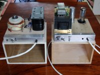
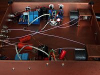
About supplies... here are mine.
At the left the LV, made from a 8.6V & 8.6V toroid (diy") ) giving two times 8.3Vdc. It has Schottky diodes, 2200μF/25, 20mH oil filled choke (3A), 3300μF/25 and a shielded connection cable to the amp.
) giving two times 8.3Vdc. It has Schottky diodes, 2200μF/25, 20mH oil filled choke (3A), 3300μF/25 and a shielded connection cable to the amp.
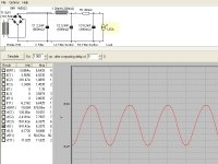
Ripple is down to 65mV. What's important: the wave shape resembles a sinus. If you just put a big cap after the diodes the waveform will be more triangular, very hard to flatten out afterwards.
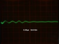
In the amplifier lays the big trick for today, invented by the illustrious Salas. The third picture shows the final ripple on the 26 filament, down to an extreme low 1mV level.
About supplies... here are mine.
At the left the LV, made from a 8.6V & 8.6V toroid (diy
) giving two times 8.3Vdc. It has Schottky diodes, 2200μF/25, 20mH oil filled choke (3A), 3300μF/25 and a shielded connection cable to the amp.Ripple is down to 65mV. What's important: the wave shape resembles a sinus. If you just put a big cap after the diodes the waveform will be more triangular, very hard to flatten out afterwards.
In the amplifier lays the big trick for today, invented by the illustrious Salas. The third picture shows the final ripple on the 26 filament, down to an extreme low 1mV level.
Attachments
What I meant is nothing so subtle, rather this: you talked about 65mV ripple, then you showed 1mV ripple. Something is responsible for that improvement. I was asking, what part of the circuit, possibly not shown, is the one responsible for going from 65mV ripple to 1mV ripple. Hope I'm not confusing the issue again.
Is is that "big trick for today" that did it?
Is is that "big trick for today" that did it?
Its the grand total noise on the notoriously sensitive #26 filament in a fully wired working preamp with everything on it, including what it can pick up from any field, and its own imbalance, plus decoupling technique. Final 0.35mV RMS AC noise on such a filament which is in circuit by being the cathode, is great, can't bother any system at all, and is skipping a nightmare that only DHT practicing DIYers can fully appreciate Iko.
Bravo Disco, you hit the nail on the head, upon first try! Without anything more dramatic than CLC and a small board with few components! The question boils down to fundamental heating strategy only, now. Is a hum free voltage source with extended and flat rudimentary impedance better than battery, tonally preferable to best Isource there is? To be or not to be (Vsource), that is the question.
Bravo Disco, you hit the nail on the head, upon first try! Without anything more dramatic than CLC and a small board with few components! The question boils down to fundamental heating strategy only, now. Is a hum free voltage source with extended and flat rudimentary impedance better than battery, tonally preferable to best Isource there is? To be or not to be (Vsource), that is the question.
Is is that "big trick for today" that did it?
He is happy, thus humoring. He means a remote sensed simplistic shunt reg that we got it to work good enough down to 1.5V only. He can share the schematic and all application info for all #26 guys now it is a sure success as far as I am concerned.
Don't know if he will deem it better than a current source on sonic grounds in the end, but its a cheap, easy and buzz free alternative at least.
Only if you see the measures people take for a hum&buzz noise free #26 preamp...expensive and copious non fully hum free horror stories abound.
Attachments
What I meant is nothing so subtle, rather this: you talked about 65mV ripple, then you showed 1mV ripple. Something is responsible for that improvement. I was asking, what part of the circuit, possibly not shown, is the one responsible for going from 65mV ripple to 1mV ripple. Hope I'm not confusing the issue again.
Is is that "big trick for today" that did it?
Ah, comme ça.
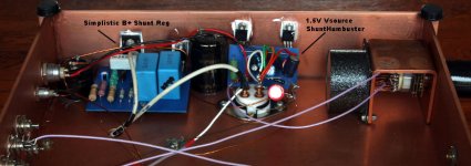
In the third picture you see two blue boards. The left is a Simplistic HV Shunt (V1.0), the right a noval Simplistic LV Shunt.
After discussing the pros and cons of voltage versus current source heating the DHT filament, Nick modeled a discrete parallel regulated 1.5V voltage source which is put in action here for the first time.
It consists of a 1.35A constant current source, isolating the 8V power supply and offering low output impedance. 0.3A is fed into a voltage source which maintains perfect smooth 1.5V on the filament. Remote sensing of the filament voltage is incorporated so an arm length of wire won't hurt.
First impressions are positive, measurements too but -hey- what a heatsink
In the weeks to come I'll investigate the results of giving more current to the sink and compare it against some known excellent competitors.Attachments
Last edited:
high frequency hum
Finally I managed to control the slight high frequency hum which troubled my listening session of 26 pre for quite some time. I found this excellent article from the site Do it Yourself - Reducing Hum about hum reduction which help me to find the problem. Funnily the issue was a filament wire crossing the plate b+ supply which inject the hum to the signal path. Moving away the wire from plate supply, got rid of the issue plus add a whole new dimension to the sound which is now more clearer and detailed than before. No wonder why people are trying so desperately to reduce hum in 26. . However, whatever the effort you put to refine 26 circuit, the end result worth all the pain all the time. Long live 26.
Finally I managed to control the slight high frequency hum which troubled my listening session of 26 pre for quite some time. I found this excellent article from the site Do it Yourself - Reducing Hum about hum reduction which help me to find the problem. Funnily the issue was a filament wire crossing the plate b+ supply which inject the hum to the signal path. Moving away the wire from plate supply, got rid of the issue plus add a whole new dimension to the sound which is now more clearer and detailed than before. No wonder why people are trying so desperately to reduce hum in 26.
. However, whatever the effort you put to refine 26 circuit, the end result worth all the pain all the time. Long live 26.the issue was a filament wire crossing the plate b+ supply which inject the hum to the signal path.
I’m glad you found the problem. I am curious though, how well filtered were the wires that crossed? I.E was the filament supply wire rectified filtered and regulated when it crossed the B+ causing the problem or raw AC or…. Same question for B+
Thanks,
Marty
I’m glad you found the problem. I am curious though, how well filtered were the wires that crossed? I.E was the filament supply wire rectified filtered and regulated when it crossed the B+ causing the problem or raw AC or…. Same question for B+
Thanks,
Marty
Marty,
Both my Filament and B+ is regulated supplies. But still I feel it is a wise idea to shielding the filament wires physically too. Even I was surprised too how this simple thing caused such an annoying disturbance. Some times I felt like smashing the whole thing when this hum appears while I am listing at low volume levels, because it was that annoying even the hum level was very low.
Hi Guys,
I’m excited to see all these posts on hum reduction and several 26 preamps all taking/taken shape. I’ve been too busy to tweak the hum out of my 26 preamp, but I did get some 9 batteries and I’ll convert it to Coolzero’s schematic based on Kevin’s suggestions. Just wondering if anyone has tried lithium batteries paralleled?
Coolzero thank you for posting all your results it’s certainly a big help for me.
I did follow Kevin’s suggestion of shielding the tubes with Al foil. This made a big difference.
Regarding filament supplies, I’m using some split bobbin EI 12V 4A transformers and getting some high current chokes wound to use in a choke input filter. I now have all the parts for Rod’s filament supply and should be able to build it over Christmas, so I’ll post the results when done.
Salas, I’d like to give that other filament supply a try, would you be able to post the details for us.
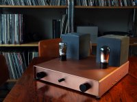
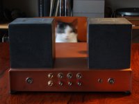
Disco, your pre looks sexy, great job. Can I ask what sort of output transformers and transformer volume control you’re using?
Marty, I hope your filament testing went well. Have you done any testing on the amplification stage yet?
Cheers,
Rich
I’m excited to see all these posts on hum reduction and several 26 preamps all taking/taken shape. I’ve been too busy to tweak the hum out of my 26 preamp, but I did get some 9 batteries and I’ll convert it to Coolzero’s schematic based on Kevin’s suggestions. Just wondering if anyone has tried lithium batteries paralleled?
Coolzero thank you for posting all your results it’s certainly a big help for me.
I did follow Kevin’s suggestion of shielding the tubes with Al foil. This made a big difference.
Regarding filament supplies, I’m using some split bobbin EI 12V 4A transformers and getting some high current chokes wound to use in a choke input filter. I now have all the parts for Rod’s filament supply and should be able to build it over Christmas, so I’ll post the results when done.
Salas, I’d like to give that other filament supply a try, would you be able to post the details for us.
Disco, your pre looks sexy, great job. Can I ask what sort of output transformers and transformer volume control you’re using?
Marty, I hope your filament testing went well. Have you done any testing on the amplification stage yet?
Cheers,
Rich
Hi Guys,
I’m excited to see all these posts on hum reduction and several 26 preamps all taking/taken shape. I’ve been too busy to tweak the hum out of my 26 preamp, but I did get some 9 batteries and I’ll convert it to Coolzero’s schematic based on Kevin’s suggestions. Just wondering if anyone has tried lithium batteries paralleled?
Coolzero thank you for posting all your results it’s certainly a big help for me.
I did follow Kevin’s suggestion of shielding the tubes with Al foil. This made a big difference.
Regarding filament supplies, I’m using some split bobbin EI 12V 4A transformers and getting some high current chokes wound to use in a choke input filter. I now have all the parts for Rod’s filament supply and should be able to build it over Christmas, so I’ll post the results when done.
Salas, I’d like to give that other filament supply a try, would you be able to post the details for us.
Disco, your pre looks sexy, great job. Can I ask what sort of output transformers and transformer volume control you’re using?
Marty, I hope your filament testing went well. Have you done any testing on the amplification stage yet?
Cheers,
Rich
Good luck Rich with your pre amp. Pretty sure that you will get good results with the schematic I have posted. 9V alkaline worked for me very well and I liked everything about this preamp. Only advice I could give you is to have well regulated supply for both filament and B+, shielded input,output and filament wires and 165V/6ma op point. These are the main points made my pre amp a success. Hope this helps.
Hi coolzero,
Thanks for the info. I have my umbilical built with no shielding between the filament supplies and the plate supply wires after the filters but before the regulators. I can shield after the regulators pretty easily so I will try that and hope it is enough.
Hi Richard
My filament boards are done and tested. I used 6.3V 5A potted transformers- low dropout diodes-lclc filtering with common mode 7mH chokes and 10Kuf caps followed by a 1085 ccs adjust pin bypassed. I could not see any hum on the scope at .2mV/ division. But that was just the filament sections on their own with the boards clip leaded together on the bench.
The signal board is done but I have not tested it. It is Kevin’s V2 circuit using battery bias on the grid and the optional grid stopper he mentioned in the write up. My biggest worries are with the power supplies and layout but I won’t really be able to test that until the assembly is almost complete.
Hi coolzero,
Thanks for the info. I have my umbilical built with no shielding between the filament supplies and the plate supply wires after the filters but before the regulators. I can shield after the regulators pretty easily so I will try that and hope it is enough.
Hi Richard
My filament boards are done and tested. I used 6.3V 5A potted transformers- low dropout diodes-lclc filtering with common mode 7mH chokes and 10Kuf caps followed by a 1085 ccs adjust pin bypassed. I could not see any hum on the scope at .2mV/ division. But that was just the filament sections on their own with the boards clip leaded together on the bench.
The signal board is done but I have not tested it. It is Kevin’s V2 circuit using battery bias on the grid and the optional grid stopper he mentioned in the write up. My biggest worries are with the power supplies and layout but I won’t really be able to test that until the assembly is almost complete.
Marty,
Let me know how your filament supply works in action. I tried many of those typical filament supplies with LM317 type regulators but all were giving hum way beyond to have a decent music listening. Hence I settled down with SMPS but like to try the conventional filament supply if it works properly.
When you have a circuit that is sensitive to pickup (as the 26 appears to be), watch out for power circuits which measure flat dc, but have pulsed CURRENTs. I mean specifically reservoir capacitors! They may only have mV ripple voltage, but ampere-level recharge pulses. This generates magnetic field (B) and may couple to your grid or anode/cathode circuit. Keep the wiring loops to those circuits small!
Best solution for filter caps, especially for filament dc supplies, is to banish them to the hinterlands with their trafo & rectifier - a metre away with a shielded cable to feed the filament is my choice.
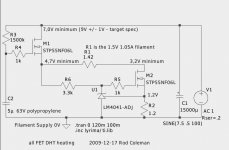
Hope you enjoy the build. If anyone considers my FET-based gyrator, note this updated schematic to fix an omitted resistor R6.
you can use the FET gyrator with the FET current source, or the BJT current source from my 300B circuit. If you substitute parts, check for oscillation with a scope and/or AM radio near to the filament.
Attachments
Salas, I’d like to give that other filament supply a try, would you be able to post the details for us.
Cheers,
Rich
http://www.diyaudio.com/forums/powe...-voltage-shunt-regulator-162.html#post2014178
When you have a circuit that is sensitive to pickup (as the 26 appears to be), watch out for power circuits which measure flat dc, but have pulsed CURRENTs. I mean specifically reservoir capacitors! They may only have mV ripple voltage, but ampere-level recharge pulses. This generates magnetic field (B) and may couple to your grid or anode/cathode circuit. Keep the wiring loops to those circuits small!
Best solution for filter caps, especially for filament dc supplies, is to banish them to the hinterlands with their trafo & rectifier - a metre away with a shielded cable to feed the filament is my choice.
Hope you enjoy the build. If anyone considers my FET-based gyrator, note this updated schematic to fix an omitted resistor R6.
you can use the FET gyrator with the FET current source, or the BJT current source from my 300B circuit. If you substitute parts, check for oscillation with a scope and/or AM radio near to the filament.
Rod,
Thanks for the advice. BTW, can I use any N-channel MOSFET substitute for your schematic like IRF810/IRF740 (which I have already in my hand)? Also, can I substitute LM4041 with any other voltage reference?
Last edited:
- Home
- Amplifiers
- Tubes / Valves
- #26 pre amp