My measuring.
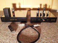
Two box (chassis) design.
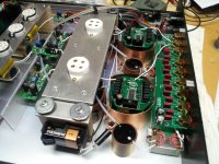
Power supply box: HT transformer, AZ1 mesh, CLCLC raw supply and two SSHV2, LT transformer, dual LT raw supply -diode bridge, C-CMC-C-L-C), 19 pin military connector.
Preamp box: (dual mono in one box) 19 pin military connector, F.A.D.A #26 tube, DN2540 cascode CCS, heater bias -10R 50W- Rod's regulator, 350nF (220nF FT3 teflon+130nF SSG-3 silver mica) coupler, S&B TX-102 TVC.
Between power supply and preamp box interconnect:
- Right LT supply non twisted 14awg
- Right SSHV2 F+ F0 twisted, S+ S0 twisted 19awg
- Left LT supply non twisted
- Left SSHV2 F+ F0 twisted, S+ S0 twisted
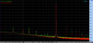
Right channel: B+ 400uV noise, bias resistor: 300uV -average- noise
Left channel: B+ 200uV noise, bias resistor: 500uV -average-noise
No shielding!
Spectrum at 6V RMS output.
Two box (chassis) design.
Power supply box: HT transformer, AZ1 mesh, CLCLC raw supply and two SSHV2, LT transformer, dual LT raw supply -diode bridge, C-CMC-C-L-C), 19 pin military connector.
Preamp box: (dual mono in one box) 19 pin military connector, F.A.D.A #26 tube, DN2540 cascode CCS, heater bias -10R 50W- Rod's regulator, 350nF (220nF FT3 teflon+130nF SSG-3 silver mica) coupler, S&B TX-102 TVC.
Between power supply and preamp box interconnect:
- Right LT supply non twisted 14awg
- Right SSHV2 F+ F0 twisted, S+ S0 twisted 19awg
- Left LT supply non twisted
- Left SSHV2 F+ F0 twisted, S+ S0 twisted
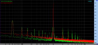
Right channel: B+ 400uV noise, bias resistor: 300uV -average- noise
Left channel: B+ 200uV noise, bias resistor: 500uV -average-noise
No shielding!
Spectrum at 6V RMS output.
Attachments
Last edited:
Hey Euro, this looks really good. Very quiet preamp indeed!
I've been playing today rearranging the HT feed at the preamp but still need to crank up the raw HT (currently at 200V) a bit higher as don't have sufficient headroom between the salas V1 and the CCS feeding the VR (150V).
Despite having only 180uV at the filaments, my output noise level is still high at -70dB
I will tweak the raw HT and salas regulator to reduce input ripple a bit further.
Ale
Very quiet tubes.....though not all...Very quiet preamp indeed!
Attachments
I had a bit of a shock today when I switched two different filament supplies for the output stage of my PSE 4P1L amp, which uses filament bias. Not quite the same as a 26 preamp, but similar issues. I started with two bench supplies to get it going and check voltages - standard Thurlby Thandar 30v, 2mA. With these the frequency response was quite even, with good vocals and midrange and rather weak bass. Then I switched to a supply with a huge 300VA toroid and choke input, 280mH, into 10,000 reservoir caps. That was quite a different sound - a lot of bass energy, very punchy but not as delicate in the midband.
I hadn't expected such an audible difference. This is going to make me take the filament supply more seriously!!
Still not sure whether to screen the interconnect from filament supply to the main signal chassis.
Andy
I hadn't expected such an audible difference. This is going to make me take the filament supply more seriously!!
Still not sure whether to screen the interconnect from filament supply to the main signal chassis.
Andy
I made an umbilical using Belden 16 gauge stranded silver plated copper in teflon for the + leads and Cardas 15.5ga copper litz for the returns. All twisted pairs. Filaments, B+ and control power (9V) all in same cable, each pair shielded with copper braid, the braids brought together at each end to one connector pin, and that pin is grounded to the chassis at both ends.
Dead quiet (<-100dB background noise, 200uV or so, although Í'm at the limit of my sound card).
Connectors are 8-pole Neutrik Speakons.
Dead quiet (<-100dB background noise, 200uV or so, although Í'm at the limit of my sound card).
Connectors are 8-pole Neutrik Speakons.
Attachments
Hey, I did some more fiddling today.
I was worried that in my zeal to get the shortest possible signal path I may have run the inputs a bit too close to the outputs, so I built shields to go around the output autoformers, out of TI-Shield, which is permalloy with copper plating on each side, so it handles both magnetic and electrostatic fields. The shields are bolted to the chassis bottom, which is chromated for good conductivity.
After I buttoned it all up I gave it a listen - WOW. The background was a little blacker than before, and instrument separation and detail was noticeable improved! I guess I was getting a little cross contamination before.
Attached is a picture of the shield implementation Well worth the effort!
Attachments
Hi Magz,
Any advantage with using Music rails on the filament supply before Rod's regulator? Any difference in sound without it?
Cheers!
Ravi
While I was in there I did some measurements for you. Voltage drop across the Music Rail is 0.5V, as specified. Noise going into the MR was 36mV RMS, coming out was 10mV RMS. So there is a decent reduction, but not huge.
I put them in because I wanted to get the noise down to the low mV level before the filament wires went into the umbilical next to the B+, and to drop a little voltage before the regulator boards, and I think 10mV RMS is acceptable for that. Rod's boards then drop it much further - dead quiet!
Hi Andy
There are many much more important points than the umbilical. For example a screen (or better two) between primaries and secondaries of your power transformers. I for example avoid toroids.
Of course it will not hurt to use a screened umbilical (Mine have screens). Connect th screen at the PSU end to PSU chassis and saftey earth.
Best regards
Thomas
Still not sure whether to screen the interconnect from filament supply to the main signal chassis.
There are many much more important points than the umbilical. For example a screen (or better two) between primaries and secondaries of your power transformers. I for example avoid toroids.
Of course it will not hurt to use a screened umbilical (Mine have screens). Connect th screen at the PSU end to PSU chassis and saftey earth.
Best regards
Thomas
Yes, the effect of screening is not very large. But it will be variable, depending on the sources of EM noise nearby.
My personal choice would be to fit the screened cable, simply because it is so easy to do, and when you are trying to achieve the best possible sound, even the smallest things can have a pleasant influence.
My personal choice would be to fit the screened cable, simply because it is so easy to do, and when you are trying to achieve the best possible sound, even the smallest things can have a pleasant influence.
If you use filament bias with my regulators, there is a strong rejection of cable noise anyway.
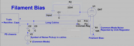
The digram shows the influences. Provided the cables run parallel, ambient noise is picked up as common-mode.
The regulator rejects common-mode noise (=grid-to-cathode noise) because Fil- is directly at ground. The regulator rejects differential noise by means of the current regulator-action.
With cathode bias, common mode noise appears across the cathode resistor, and so produces a current that runs through the cathode capacitor. This may well add to problems presented to electrolytic capacitors, with their high parasitic inductance, and effective resistance. But I imagine that no-one here is using cathode bias with a capacitor now, anyway.
Attachments
Another question, what's the optimum size cap to put in the signal chassis at the input of the cable? Should you put 10,000uF here for example, or less or more?
With any of my PCB-based Regulators, reducing the ripple to 80-140mV should be enough, even for line amps. So LC with 10mH or more and 10000uF is easily good enough.
Of course, this all has to do with differential mode ripple and noise.
When you use a high-capacitance trafo (eg Toroid) the noise that gets in is common-mode. The regulator will reject this, but not completely. Hence the recommendation for split-bobbin trafos.
The old 2004 Regulator circuit rejects CM and DM noise much less effectively.
Is there any point in twisting the pairs of wires in the cable?
Only if the cables pass by a strong noise source, like a power trafo. Running them parallel & close is enough.
Replaced the HT filtering stage with a salas SSHV2 regulator (185V output) and then the CCS with the glow tubes (150V and 15mA each channel).
When the salas board was under test hanging with a couple of test leads and not fitted in the preamp (probably at 15 cm with some test leads) the output noise was very low (-85dBV). Happy with the results, fitted the Salas SSHV2 board into the preamp really close to the glow tubes, soldered final cables and when tested again surprisingly the noise went up again to -70dBV....
Are the glow tubes responsible for this due to being so close to the salas PCB or shall I look to the noise source anywhere else?
Ale
Yes but with a CCS in between. So: SSHV2 -> CCS -> VR
They look really cool! Strange thing was that when did first test over existing preamp it was dead quiet, when fitted the SSHV board in the preamp, noise went back.
I will try to replicate situation by removing physically the board from the preamp....
Ale
They look really cool! Strange thing was that when did first test over existing preamp it was dead quiet, when fitted the SSHV board in the preamp, noise went back.
I will try to replicate situation by removing physically the board from the preamp....
Ale
I said it before. The VR tubes generate their own noise, higher than the noise of the Salas shunt reg. I think it completely defeats the purpose of the shunt regulator to put the VR tube last. The CCS has no effect. I too like the look of the VR tubes.
As for the higher noise after you installed the shunt reg in the box; where did you measure the noise before and after, on the tube anode?
As for the higher noise after you installed the shunt reg in the box; where did you measure the noise before and after, on the tube anode?
Iko,
found the issue! It was a ground loop introducing noise. The problem was that I omitted grounding the output as I'm not using the differential connection now so return was through amplifier's earth. I grounded with a pair of test clips the return of the output cables and noise is completely gone!
Will do proper measures again to reflect this, am a happy man at last.
BTW, the CCS has a good noise rejection capability as Morgan Jones clearly showed in his statistical regulator. I did the same but replaced zeners with the nice glow tubes. My tests were very promising:
http://www.bartola.co.uk/valves/2012/08/16/russian-voltage-regulator-test/
Ale
- Home
- Amplifiers
- Tubes / Valves
- #26 pre amp