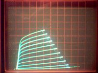
I haven't seen any datasheets with curves for the 6HJ5, so here are some curves. No matter what brand name is on them, they all seem to be made in some "LYFA" factory, probably Raytheon.
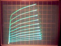
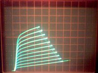
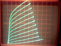
Pentode: 50 V/div horiz., 50 mA/div vert., 115 V on g2, 1.85 V steps on g1
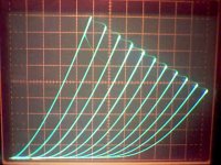
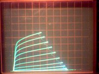
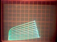
Triode: 20 V/div horiz., 50 mA/div vert., 3.8 V steps on g1
The triode curves look nice, the pentode mode doesn't really look very remarkable, but strange cancelations do occur in P-P. Looks suitable for g2 drive with 540 mA at 135 V g2, & 60V plate spec'd on the datasheet.
Don
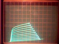
Pentode: 50 V/div horiz., 50 mA/div vert., 115 V on g2, 1.85 V steps on g1
Triode: 20 V/div horiz., 50 mA/div vert., 3.8 V steps on g1
The triode curves look nice, the pentode mode doesn't really look very remarkable, but strange cancelations do occur in P-P. Looks suitable for g2 drive with 540 mA at 135 V g2, & 60V plate spec'd on the datasheet.
Don
Attachments
I haven't seen any datasheets with curves for the 6HJ5, so here are some curves. No matter what brand name is on them, they all seem to be made in some "LYFA" factory, probably Raytheon.
All of mine are marked "LYFA" and branded RCA. I also have one 6HD5, Motorola brand. It is also marked "LYFA". The 6HD5 seems to work the same as the 6HJ5 except that pin 2 is not connected. Thanks for the curves. Yep, screen drive will get tested when I have more tubes. I have already discovered that pushing the limits in screen drive will make fireworks!
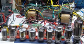
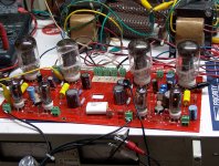
I forgot to post this picture last night. I was having too much fun watching my speakers jump around on the bench! It shows a few of the tubes that I would likt to run in this amp. Left to right...6GF5, 6HE5, 6JN6, 6GV5, 6HJ5, 6HF5, 6LR6, 6KD6, and the 6LW6. Many have already been in the amp, and the remaining ones will need require more board modifications. Check out the size of the 6LW6 and you know why I just got to try it!
Attachments
That 6GF5 looks like its shaking in its boots next to all those big bad boys.
"I have already discovered that pushing the limits in screen drive will make fireworks!"
That reminds me, I was going to try the g2 drive with scaled down (by Mu) g1 drive combo on the curve tracer. Only half as much g2 drive required that way. Should be safer and easier on the driver.
The 21HB5A, 21KA6, 21GY5 or 21JZ6 are available at $1 and look interesting.
The triode curves look nice, the pentode mode doesn't really look very remarkable, but strange cancelations do occur in P-P. Looks suitable for g2 drive with 540 mA at 135 V g2, & 60V plate spec'd on the datasheet.
Nice curves. Pentode looks a little kinky.
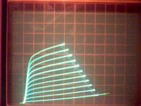
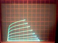
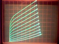
Here it is, g2 drive with scaled g1 drive on the 6HJ5. I used a 15K resistor from g2 down to g1 and a 4K resistor to ground or a neg bias. Tube g2/g1 Mu is supposed to be 4.2. 50 V/div horiz., 50 mA/div vert., 5.3 V steps on g2.
First is with 0V DC on the bottom of the 4K, then -5V, -10V, -12V, and -16V.
Last one is with +20V on the bottom of the 4K resistor. I guess 0V is safest and still linear.
First is with 0V DC on the bottom of the 4K, then -5V, -10V, -12V, and -16V.
Last one is with +20V on the bottom of the 4K resistor. I guess 0V is safest and still linear.
Attachments
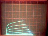
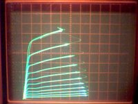
Here is g2 drive only, g1 at 0V. Scale factors and steps the same as above. Compare with the 1st photo above. Clearly the scaled g1 contribution above makes a difference. Maybe more linear even? Doesn't seem to be doubling the current over g2 only though.
On further checking, it appears that the increased current above is simply due to the DC drop on the 4K putting +1V on g1 there versus 0V here. It also looks like having g1 go positive is drawing enough current to kill the scaling so that hardly any step drive is getting to g1.
Back to the drawing board. I either have to re do the resistor ratio to account for g1 current draw, or put a Mosfet driver on g1.
Attachments
Last edited:
That 6GF5 looks like its shaking in its boots next to all those big bad boys.
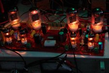
Yeah, they ran and hid under the bench when I turned on the soldering iron. So, I grabbed the next biggest tubes. These are 6JB5/6HE5/6JC5. another member of this forum called them as good as or better than a 6V6. I have 3 different versions with 3 entirely different constructions. The RCA's do indeed look like a RCA 6V6 only a bit bigger. I have 4 of the GE's which have bigger plates than the RCA's so that's what is in the amp now. The Sylvanias are even bigger, but I only have 2.
These need some more screen voltage to get anywhere. On 150 volts I got 10WPC. On 200 volts I got 18 WPC. On 250 volts I got 25 WPC with 400 volts on the plate and a 6600 ohm load. There might be more left in these tubes but I stopped turning knobs and hooked up the music for a few minutes before Lost came on.
25 WPC is 6db less power than 100 WPC. On my speakers the absolute volume difference between the two is less than you would think because once the speaker cones are moving as far as they will go, more power just makes more distortion. The 100 WPC version does slap the speaker cones around with far more authority that the 25 WPC version. This is most noticible on dynamic music like drum hits.
Again I must issue this WARNING. These tubes require some serious modifications including cutting runners to use them. The runners that need cutting are under the tube sockets so the board surgery needs to be done before construction. Yeah, I planned in advance to use this board for some tube "testing".
Attachments
Back to the drawing board. I either have to re do the resistor ratio to account for g1 current draw, or put a Mosfet driver on g1.
I have tried this idea before. It led to some exploded mosfets. I believe that the solution here is two mosfets, one on each grid with seperate DC bias and AC gain controls on each. I have actually implemented this idea and even taken it one step further. I can drive the two grids out of phase from a P-P driver board.
I built this breadboard last August but it sits on the bench untested. Someday....
Well since the step generator is capable of driving amperes for testing bipolars, I just opted for the most elegant approach: Brute Force. I made the resistor divider 300 Ohms from g2 down to g1 and 100 Ohms from g1 down to ground (cathode).
Now some decent results: (20 ma/div, 50 V/div, 5.3 V step)
1st: g2 and scaled g1 drive
2nd: g2 drive only
3rd: g2 drive only, but I changed the vert. scale here to 10 mA/div to double the size, for linearity comparison with the 1st plot.
Looks like each grid is doing half the work now, and looking good for linearity. Only half the g2 voltage swing is needed this way, versus plain g2 drive. I also tried varying the bias voltage on the bottom resistor and 0V looks best.
Scaled g2g1 drive is what I'm going to use now. Look how clean those curves look now too compared to the earlier g1 curves (the ones with "kinks").
Attachments
"It seems like to two grids would have wildly different drive requirements."
They do, that's what the part about "scaling" is about. The g1 grid gets driven by 1/Mu (Mu_g2g1) of the g2 signal, so each grid is doing equal work. For example, the 6HJ5 has a Mu or 4.2. So the g1 drive signal will be 1/4.2 of the g2 drive signal. As you can observe from the scaled g2g1 test above, each grid does 50% of the work for controlling current. This way the g2 only needs 1/2 the swing it would normally need in g2 only drive, so this makes the driver stage much easier. I only had to use 55V above for operating the 6HJ5 g2 (and 55/4.2 V for operating g1). Both grids are operating in grid current territory too, with g2 likely the lowest Z to drive. So, yes, Mosfet followers will be needed.
Wrenchone:
There don't seem to be any data sheets for the 35LR6. Have you found one?
I can smoke up some curves here if needed.
Last edited:
I haven't seen any curves for the 6LR6 and siblings, and I only have data for the tube in my much-tattered RCA catalog (in several pieces due to age and overuse). However, what I see there tends to indicate that it is similar to the popular 6JE6/6LQ6. I was lucky enough to score a bunch of 35LR6 at a scandalous price from AES before they recovered their senses and jacked the price up to something near the going rate for other tubes of their plate dissipation rating. If you want to run some curves, it'd be interesting.
Ouch! It looks like you could really tone down the G2 drive requirements with a light touch of G1. Reference my thread "The Bursar", which shows a preliminary design for a P-P amp with pentode front end and autotransformer phase splitter driven by a source follower. I've since made some improvements in the bias string to better power the source follower and input pentode screen. With G1 augmentation, the basic front end could be used to make a simple and monstrous sweep tube P-P. I don't see any reason why Schade -style feedback wouldn't work with screen-driven tubes. However, I could just as well be less ambitious and wrap feedback around from the output the usual way. That's what I'll try first with "The Bursar".
- Home
- Amplifiers
- Tubes / Valves
- Posted new P-P power amp design