Hello all,
This is my first post, although I've been a member now for a while. As a hobby,I've been studying "electronics" and "tube electronics" for a couple of years now. My goal is to be able to design and build great sounding components for my enjoyment and that of my family and friends. I am still far from my goal. I'm afraid I'm seriously mathematically disinclined, and I'm really stubborn about asking for help.
I've recently built Fred Nachbaur's phono-pre and I've just finished "Frank's 6SN7" line level pre. Both of these were built with about 97% salvage materials, in the interest of minimizing the cost of learning. I did make a walnut and aluminum chassis for the new pre though.
Since Frank's pre schematic doesn't really include a power supply, I'm a little concerned about the heater-cathode voltage since I cobbled together the power supply from on-hand components.
I've searched high and low, and maybe I'm not using good search terms, but I can't find a direct description of how to measure "heater cathode voltage". I mean, seemingly all tubes have a maximum "heater-cathode voltage" which may be X volts positive or negative. Everybody must already know how to measure this or else there would be some better references on the web. I however, do not.
Would someone please point me to a reference of how to measure this parameter or provide their own description?
Thanks.
I don't quite get what you mean
the max h-k voltage is a parameter of the tube you are using, and you design your heater supply to address that if required. In the case of your 'sn7, a quick glance at the datasheet shows a max h-k of 100v.
Since the 'sn7 cathodes in Franks design are both at different voltages it may be best to "float" the heater supply.
I am not sure what you really mean by "how to measure" h-k voltage.
If you literally mean how to measure it in an existing amp, then you measure it the same way you measure any voltage, one meter probe on cathode pin, the other on either heater pin. Dont worry about which heater pin, the difference of a few volts is insignificant.
But you probably already know that.
If you mean how to determine what the h-k voltage would be by looking at a schematic, do 2 things.
1) look at the transformer winding. If one or the other winding, or a center tap, is tied to ground then the k-h voltage is just the cathode voltage ( notice I said k-h this time, note the polarity ).
Or if the center tap is connected to ground through a pot, or some resistors. All virtually the same thing.
If the winding or center tap is connected to a dc voltage, then that will be added to, or subtracted from, the cathode voltage, paying attention to the polarity.
2) look at the cathode circuit. figure out the cathode to ground voltage.
Now add/subtract the cathode - ground voltage to the heater-ground voltage, paying attention to the polarity.
It takes longer to say than to do, I think so anyway.
Very simple : you put an programmable DC at least 300V max source between heater and cathode of that tube and increase the voltage from 0V till they do a short circuit and the tube are not usable !bobbyq said:Hello all,
This is my first post, although I've been a member now for a while. As a hobby,I've been studying "electronics" and "tube electronics" for a couple of years now. My goal is to be able to design and build great sounding components for my enjoyment and that of my family and friends. I am still far from my goal. I'm afraid I'm seriously mathematically disinclined, and I'm really stubborn about asking for help.
I've recently built Fred Nachbaur's phono-pre and I've just finished "Frank's 6SN7" line level pre. Both of these were built with about 97% salvage materials, in the interest of minimizing the cost of learning. I did make a walnut and aluminum chassis for the new pre though.
Since Frank's pre schematic doesn't really include a power supply, I'm a little concerned about the heater-cathode voltage since I cobbled together the power supply from on-hand components.
I've searched high and low, and maybe I'm not using good search terms, but I can't find a direct description of how to measure "heater cathode voltage". I mean, seemingly all tubes have a maximum "heater-cathode voltage" which may be X volts positive or negative. Everybody must already know how to measure this or else there would be some better references on the web. I however, do not.
Would someone please point me to a reference of how to measure this parameter or provide their own description?
Thanks.
This parameter may be measured only by destroying the tube !
Did you understand ?
Thank you both for your replies. This helps, but I still need a little further clarification. Robert, your initial description is what I was looking for.
To float the heater supply means to not connect the center tap to ground, correct?
When I don't connect the center tap to ground, I get -10vdc to cathode on pin 3 and +14vdc to cathode on pin 6. This is measured with the common or ground VOM lead on the heater and positive lead to the cathode..
When I connect the center tap I get +3.8vdc on 3 and +128vdc on 6, using the same VOM lead connections. If I reverse the lead connections then the measurements change to negative DC.
How do I know which is the correct method for connecting the leads? The 6SN7 permits 100vdc "heater positive with respect to cathode" and 200vdc "heater negative with respect to cathode". I find these terms confusing.
I would prefer to have the heater winding center tap grounded, as this reduces hum, although the hum is already pretty low. However, if I am measuring the voltage correctly, it seems I'm exceeding the h-k voltage spec. On the other hand, if I'm measuring it backwards, then I'm ok. So which way should I connect the measurement leads?
so don't float the heaters - elevate them
connect the centre tap to an elevated voltage source - it doesn't require current, just a voltage reference. Typically, you would aim to be at around 66% of the h-k max, but as long as you are within the range in this situation its not critical.
One trick is to reference the heaters to the cathode itself take the centre tap back to the junction of your bias and load resistors in the cathode of the cathode follower. Again, through a high value resistor, since we don't want current from the heaters entering this circuit!
Sorry about the messy, confusing diagram - ask if you need explanation. Others, feel free to criticise and comment.
Attachments
In addition to the cathode trick above, you can also use a simple voltage divider from your B+ to reference your heater center tap. Use high value resistors (since you don't want to draw any meaningful current from the power supply) and select the R values to get the heater voltage raised to be comfortably within the h-k rating for the tube.
The basic idea is show in post #173 of this thread for the Aikido heater bias on Bas Horneman's PS PCB:
http://www.diyaudio.com/forums/showthread.php?s=&threadid=60585&perpage=50&pagenumber=4
The basic idea is show in post #173 of this thread for the Aikido heater bias on Bas Horneman's PS PCB:
http://www.diyaudio.com/forums/showthread.php?s=&threadid=60585&perpage=50&pagenumber=4
For the voltage divider off of B+, which is about 250V, I used a 330k and 100k and connected my heater center tap to the junction through another 100k. I now have +71vdc to cathode on 6 and -55 or so to the one on 3. With all inputs unterminated and volume at max, hum has gone from 42 millivolts to 28-30. I didn't measure it before, but listening on a headphone it sounds about the same as when I had the heater tied directly to ground.
Thanks again for all the help.
Thanks again for all the help.
A reduction by ~1 dB (~30%) is pretty much inaudible. This just shows that [majority of the] hum you're experiencing isn't caused by the diode action of heater with regards to cathode, although some is and you're better off using it. BTW, do improve it by adding a smallish capacitor (say 10 uF) and perhaps by lowering resistance as far as you can afford it (at least halve it while you're experimenting).
Then trace the hum - check the anode voltage with grid tied to a fixed potential (= grounded). If there is no hum present, then your source of hum is the input cable (it's position, orientation, lack of shielding, etc.). If there is still hum present, your anode supply filtering sucks.
Then trace the hum - check the anode voltage with grid tied to a fixed potential (= grounded). If there is no hum present, then your source of hum is the input cable (it's position, orientation, lack of shielding, etc.). If there is still hum present, your anode supply filtering sucks.
Please help..
I too am very confused about Heater-Cathode Voltage I have built Frank's 6SN7
using Russian 6N8S.
Just a tube noob on my second build.
So I take voltage readings from pin 6 to heater pins.
I get 114 and 120.4 volts on one tube and 118.9 and 125.4 to heater pins on the other tube.
So is that above the limit of 100 volts. Right??
I'm running the heaters in series at 13 volts DC.
Preamp sounds great for now, I'm just concerned about the lifespan of the tubes and my be stripping them?
Any information would be greatly appreciated.
Robert
Attachments
It is, but I wouldn't worry about it.
I've never elevated a heater in any design and I'm had 2 failures (noise tube) out of over 200. One was 5670, other was 6N3P.
FWIW, some 6N8S datasheets say max 250V B+. I run some of mine from 600V (cold tube, 350V plate hot) and never has a hint of an issue.
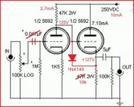
If you're truly worried, you can "elevate" the heaters if the power source is isolated (like most transformers and some SMPS). Tie 300k to B+, tie 75k to that, the other end of 75k to ground. Connect middle point of 300k/75k to heater where you would NORMALLY connect it to ground.
Again. Probably not required at all though for life/safety.
It looks like this. You can use the values in this picture insteadf of 300k/75k if you like. The values aren't critical but most people try for ~80VDC+ Cap is bonus but completely unnecessary.
Likewise, the 100R aren't required. Just tie it to one end of the heaters.

Some people report lower noise with an elevated heater though. YMMV.
Koda
I've never elevated a heater in any design and I'm had 2 failures (noise tube) out of over 200. One was 5670, other was 6N3P.
FWIW, some 6N8S datasheets say max 250V B+. I run some of mine from 600V (cold tube, 350V plate hot) and never has a hint of an issue.
If you're truly worried, you can "elevate" the heaters if the power source is isolated (like most transformers and some SMPS). Tie 300k to B+, tie 75k to that, the other end of 75k to ground. Connect middle point of 300k/75k to heater where you would NORMALLY connect it to ground.
Again. Probably not required at all though for life/safety.
It looks like this. You can use the values in this picture insteadf of 300k/75k if you like. The values aren't critical but most people try for ~80VDC+ Cap is bonus but completely unnecessary.
Likewise, the 100R aren't required. Just tie it to one end of the heaters.
Some people report lower noise with an elevated heater though. YMMV.
Koda
Last edited:

Thanks for the drawing.It is, but I wouldn't worry about it.
I've never elevated a heater in any design and I'm had 2 failures (noise tube) out of over 200. One was 5670, other was 6N3P.
FWIW, some 6N8S datasheets say max 250V B+. I run some of mine from 600V (cold tube, 350V plate hot) and never has a hint of an issue.
If you're truly worried, you can "elevate" the heaters if the power source is isolated (like most transformers and some SMPS). Tie 300k to B+, tie 75k to that, the other end of 75k to ground. Connect middle point of 300k/75k to heater where you would NORMALLY connect it to ground.
Again. Probably not required at all though for life/safety.
It looks like this. You can use the values in this picture insteadf of 300k/75k if you like. The values aren't critical but most people try for ~80VDC+ Cap is bonus but completely unnecessary.
Likewise, the 100R aren't required. Just tie it to one end of the heaters.
View attachment 1074625
Some people report lower noise with an elevated heater though. YMMV.
Koda
A picture is worth more than a thousand words.
Have a Great Weekend
Elevating the heater just means to make the heater more positive with respect to the ground. Your circuit, you have ~125V at the cathode making hk voltage of 125V provided you grounded one side (or a centre tap) of the heater supply... Don't float the heater even if it works... It's the best way to find "Gremlins" in your amp later on LOL
If you tie the heater to the B+ through resistors instead of grounding it, you can lower that difference. For instance, 125V - 80V = 45V. within spec of the 100V they say on the sheet.
I find the only time I would really need to elevate is if I'm making a cathode follower with a B+ higher than 350V...
A 0.1uF or 0.22uF (with adequate voltage rating) can effectively be used instead of a 22uF capacitor. These low value caps are also usually film caps which are better at filtering high frequency noise than electrolytics. Just FYI.It is, but I wouldn't worry about it.
I've never elevated a heater in any design and I'm had 2 failures (noise tube) out of over 200. One was 5670, other was 6N3P.
FWIW, some 6N8S datasheets say max 250V B+. I run some of mine from 600V (cold tube, 350V plate hot) and never has a hint of an issue.
If you're truly worried, you can "elevate" the heaters if the power source is isolated (like most transformers and some SMPS). Tie 300k to B+, tie 75k to that, the other end of 75k to ground. Connect middle point of 300k/75k to heater where you would NORMALLY connect it to ground.
Again. Probably not required at all though for life/safety.
It looks like this. You can use the values in this picture insteadf of 300k/75k if you like. The values aren't critical but most people try for ~80VDC+ Cap is bonus but completely unnecessary.
Likewise, the 100R aren't required. Just tie it to one end of the heaters.
View attachment 1074625
Some people report lower noise with an elevated heater though. YMMV.
Koda
- Home
- Amplifiers
- Tubes / Valves
- Heater-Cathode Voltage