Wavebourn said:I have to catch up fast, but please expect at least 2 months lead time. Orders will be completed on FIFO basis.
Anatoliy
That’s good Anatoliy,
I hope I’m not at the end of the line.
I wish you all the best and I’m happy to see the success, you really deserve it.
Cheers
S
stinius said:
That’s good Anatoliy,
I hope I’m not at the end of the line.
I wish you all the best and I’m happy to see the success, you really deserve it.
Thank you Stein; I've started designing your version already.
If you prefer I can report how it is going in this thread.
Anatoliy
Wavebourn said:
Thank you Stein; I've started designing your version already.
If you prefer I can report how it is going in this thread.
Anatoliy
That's OK by me. ( meaning: that would be nice)
S
Ok; here are Filter inductors. There will be 3 of them for effective power usage and no heavy rectifier peaks (also, I heard as if Europa is going to accept new regulations that don't allow peak diode rectification):
http://www.alliedelec.com/Search/ProductDetail.aspx?SKU=9670197&MPN=C-59U
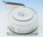
Transformers (3 of them) will be approximately like this. Please let me know if yours will have different sizes:
http://cgi.ebay.com/500W-Toroid-Toroidal-Transformer-Int-Power-amplifier_W0QQitemZ250439486758
I will use Aerovox filter capacitors.
Channels for power efficiency will draw current from a power supply in counter - phase, so please assume grounding of speaker cables will be not allowed (different channels will have different grounded posts).
Why do I start from power supply, because without a corresponding power supply any amp may be spoiled. Also, I have to design layout first, before ordering heatsink and other chassis parts.
http://www.alliedelec.com/Search/ProductDetail.aspx?SKU=9670197&MPN=C-59U
Transformers (3 of them) will be approximately like this. Please let me know if yours will have different sizes:
http://cgi.ebay.com/500W-Toroid-Toroidal-Transformer-Int-Power-amplifier_W0QQitemZ250439486758
I will use Aerovox filter capacitors.
Channels for power efficiency will draw current from a power supply in counter - phase, so please assume grounding of speaker cables will be not allowed (different channels will have different grounded posts).
Why do I start from power supply, because without a corresponding power supply any amp may be spoiled. Also, I have to design layout first, before ordering heatsink and other chassis parts.
Wavebourn said:Ok; here are Filter inductors. There will be 3 of them for effective power usage and no heavy rectifier peaks (also, I heard as if Europa is going to accept new regulations that don't allow peak diode rectification):
http://www.alliedelec.com/Search/ProductDetail.aspx?SKU=9670197&MPN=C-59U
Transformers (3 of them) will be approximately like this. Please let me know if yours will have different sizes:
http://cgi.ebay.com/500W-Toroid-Toroidal-Transformer-Int-Power-amplifier_W0QQitemZ250439486758
I will use Aerovox filter capacitors.
Channels for power efficiency will draw current from a power supply in counter - phase, so please assume grounding of speaker cables will be not allowed (different channels will have different grounded posts).
Why do I start from power supply, because without a corresponding power supply any amp may be spoiled. Also, I have to design layout first, before ordering heatsink and other chassis parts.
I'll use different transformers, but maybe not that different in size.
I'll give you the exact measurements.
The rest is ok.
Wavebourn said:Thanks! What distances are between mounting holes and their diameters?
Did you get my e-mail? I need to pay to Motoshiba, IRF, and some others to get parts...
Edit: never mind about holes, I see 130x130 are between holes.
I’m on a laptop in the garden now and haven’t checked the email, but you have my email address so I’m sure I have received it. I’ll check it and respond.
Yes 130x130mm are between holes.


Hmmm... Unexpected problem: I forgot that Hammond transformer I already mounted on the chassis for the prototype has 345-0-345 secondary. Now, if I can't find a corresponding reactor (I had it somewhere in my barn) I will need to search for another transformer, or to buy one.

")

Drilling holes in the power supply PCB... However, it is time consuming task to make PCB such a way, but it would cost $150 for one board and few days to wait. Hundred of PCBs for prototypes to save money on quantity is not a good idea: prototype is a flexible thing and may be changed many times until is done.

Etching the PCB in a Ferric Chloride that I'm afraid may be already weak. One of places where it can be bought is there: http://www.j-tron.com/category/PC_Board_Making_Chemicals,_Accessories.html
It comes in powder form, and needs to be dissolved in water slowly and carefully, since water may start boiling. Rubber gloves and eye protecting glasses are needed, the work should be done in well ventilated place. It must be stored and used in glass or plastic vessels.
However, when I bought the powder it contained an instructions' paper with corresponding warnings.
While waiting for PCB to be done I drew a simplified concept of an output stage. Version 1 is what I used in Tower-II, Version 2 is what I am going to try in Tower-IV. Tower-III does not have a bootstrapping source follower on top, for a power efficiency.
A counter-modulated current source on bottom minimizes current variations through an output source follower, while an additional source follower on top minimizes voltage variations between it's drain and source. As the result, distortions caused by capacitive load of the previous (tube) stage, of variations of capacitances and transconductance with voltage, current, power (hence temperature) are minimized without any additional feedback, hence without additional high order distortions.

A counter-modulated current source on bottom minimizes current variations through an output source follower, while an additional source follower on top minimizes voltage variations between it's drain and source. As the result, distortions caused by capacitive load of the previous (tube) stage, of variations of capacitances and transconductance with voltage, current, power (hence temperature) are minimized without any additional feedback, hence without additional high order distortions.
Wavebourn said:The PCB is not ready, but while waiting for it I've got a crazy idea: to use similar source followers both for input for and output stages, with a step-up transformer between them. The result will be a "No-GNFB" amp, but it's for a SS forum.
You can get a little more life out of FeCL by heating it up to about
100 degrees F and bubbling air through it as you etch. The etch
rate increases with temperature. Time to get out the fishtank heater...
Michael
- Home
- Amplifiers
- Tubes / Valves
- Wavebourn Tower-III High-end hybrid amp