This very high end preamp is retailing in Hong Kong for
HK$ 450,000. The power supply is advertised as even better than battery no matter what AC main you put in. The ps is internationally patented.
Any idea what is the circuit like, the impedance of the output transformer, etc
Audiohifi
HK$ 450,000. The power supply is advertised as even better than battery no matter what AC main you put in. The ps is internationally patented.
Any idea what is the circuit like, the impedance of the output transformer, etc
Audiohifi
Audiohifi said:Any idea what is the circuit like
If patened, then there are patent docs to look at. That will tell us a lot.
dave
Audiohifi said:The ps is internationally patented.
"Patent applied for". They sound like simple series regulators. AN must be very proud.
Re: Re: New Audio Note M10
http://www.tubecad.com/2007/06/blog0110.htm
analog_sa said:
"Patent applied for". They sound like simple series regulators. AN must be very proud.
http://www.tubecad.com/2007/06/blog0110.htm
analog_sa said:The M10 is probably a bit different but the older preamp shuntregs around the ECL82 are very similar to the old patent. I would never have guessed that the addition of a single capacitor is patentable.
Hey, that's a major change in the patent world. Any change is patentable

450,000 Hong Kong Dollars is about £35,000 (UK, pounds Stirling) !!!!!!!!!!!!!!
For this http://www.audionote.co.uk/products/preamp/m10_01.shtml ???
Even allowing for custom cases for the pre and psu, heavy transformers and chokes, and decent pots, you could knock up something like that for £1600 or so.
Oh well, long live capitalism...
: )
For this http://www.audionote.co.uk/products/preamp/m10_01.shtml ???
Even allowing for custom cases for the pre and psu, heavy transformers and chokes, and decent pots, you could knock up something like that for £1600 or so.
Oh well, long live capitalism...
: )
Gordy said:Oh well, long live capitalism...
The high price is necessary to cover the patent fees

Gordy said:450,000 Hong Kong Dollars is about £35,000 (UK, pounds Stirling) !!!!!!!!!!!!!!
For this http://www.audionote.co.uk/products/preamp/m10_01.shtml ???
Even allowing for custom cases for the pre and psu, heavy transformers and chokes, and decent pots, you could knock up something like that for £1600 or so.
Oh well, long live capitalism...
: )
This is obscence pricing!
Cost more than the Mercedes C class!
Consider the amount of engineering and patents Mercedes had put into a car.
Also, pound for pound, with that money you get 3000 lbs of metal vs 30lb for a preamp.
Don't mention exotic metals in the amp, the catalytic coverter in a car has more precious rare metals than a preamp.
There is a legend (regardless ,well or wrongly earned ,also not all people with money are idiots without taste or ear.
Some of them buy it because it's an Audio Note and some because they already had stuff with phase control, mute , remote display and many other things and they prefer to spend money on AN because it sounds the way they like it. (I'm not saying better)
Comparison to a car is a nonsense.
Regards
,also not all people with money are idiots without taste or ear.Some of them buy it because it's an Audio Note and some because they already had stuff with phase control, mute , remote display and many other things and they prefer to spend money on AN because it sounds the way they like it. (I'm not saying better)
Comparison to a car is a nonsense.
Regards
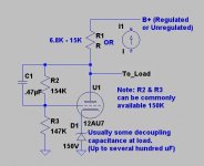
Well I am somewhat surprised because this shunt regulator sounds extraordinarily similar to a design I used over 20yrs ago in my first pre-amplifier design, and I considered it to be at best derivative of prior art - not that I could have afforded to patent it in any event.
I have included an example of the earliest design (which dates from 1988 - 89 time frame) which I used in only the prototype pre-amplifier design, and which I subsequently determined did not meet my performance objectives. A high transconductance high mu type like the 5842 would perform much better in this particular circuit. (The D3A triode connected is another good choice.) A moderate mu type like the 5687 ought to be interesting enough particularly with a CCS instead of a simple resistor to the supply.
Not identical perhaps, but I suspect more than a germ of the idea is there, and this very topology is shown on John Broskie's site.
Edit 1: The 12AU7 is a terrible choice for this circuit, due to low gm, low mu, and not so low rp - hence not recommended. It was I thought, the best choice based on what I knew at the time, and what was then commonly available to prospective customers..
Remember SPICE was not readily available, nor machines capable of running it, therefore everything was calculated, it worked but conferred little benefit I could measure and none I could hear. There really wasn't enough loop gain to do the job well, dc spot on - ac performance mediocre. The supply on the other side of that resistor was a good series pass design that I still use to this day.
Edit 2: The output would be about 300V @ a few mA or more, and in the input supply would be between 360 - 400V ideally. I used one of these to drive each circuit block in the pre-amplifier.
Attachments
kevinkr said:Well I am somewhat......
well - ya need old fart to recognize old fart
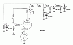
attached shunt from audio Innovations L2 , later modified iteration ;
I think it's still somewhere on AN UK site .
TP2 is feed point to load
Attachments
Zen Mod said:
well - ya need old fart to recognize old fart
attached shunt from audio Innovations L2 , later modified iteration ;
I think it's still somewhere on AN UK site .
TP2 is feed point to load
I use the 5651 and 85A2 as references in both shunt and series pass regulators, and guess what..

I guess what they say is true, there truly is nothing new under the sun, and I guess more to the point is whether or not AN should have been able to patent this concept at all. Clearly not original.


Audiohifi said:Hi Kevin
I have one of your schematics dated 30 August 1998 titled Bal_pre PSU.
You use 6BQ5 and a12AX7. I wonder is this something similar
I can scan and post if you allow me to do so
Thanks
Please, post it
- Status
- This old topic is closed. If you want to reopen this topic, contact a moderator using the "Report Post" button.
- Home
- Amplifiers
- Tubes / Valves
- New Audio Note M10