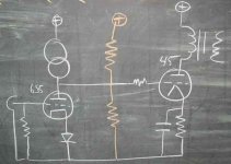
I was working on someone's amp the other day. It is a 6J5 DC coupled to a 45. The owner wants, for now, to keep the tubes and the topology as is. But, we added a CCS load and LED bias to the first stage to try to improve it a little. However, I am concerned that if something goes wrong, that the second stage could be damaged. Can anyone comment on the wisdom of adding a couple of resistors to form a voltage divider (the orange resistors shown) to make sure that the output tube maintains bias in the event of the driver crapping out? This is done on the Aikido, but I am unsure of how the larger output tube changes things. I also assume that this will defeat some of the benefits of the CCS, though with high enough value resistors, the reduced load should be negligible. Thought?
Attachments
dsavitsk said:Yeah, that's a good idea. Something like a 100mA slow blow perhaps?
You could always replace the cathode resistor of the output stage with a CCS . That would prevent any nastiness
316A
Funny I should find this thread, its my amp in question (Hey Doug ")
I would love to hear other comments regarding the use of fuses on the plate of the output tube to protect it from the bias running away. I don't think I hear any sonic degradation but the idea of the signal and all that voltage and current running through the fuse and contact holders could be of concern. I will add that regardless I am very highly appreciative of dsavistk's efforts and mindfulness of my safety
I would love to hear other comments regarding the use of fuses on the plate of the output tube to protect it from the bias running away. I don't think I hear any sonic degradation but the idea of the signal and all that voltage and current running through the fuse and contact holders could be of concern. I will add that regardless I am very highly appreciative of dsavistk's efforts and mindfulness of my safety
Been there, blown that. (not with a 45 though)
No, the CCS will defeat the resistors. Lets say the CCS is set to 10 mA. Then the driver tube goes dead, or worse someone pulls it out of the socket (or the socket goes intermittent). The 10 mA must go somewhere. It will go directly into the grid of the 45. Any resistor small enough to absorb a significant amount of this current will kill the signal.
If you were to install a fuse, I would put it in the cathode circuit. This way the grid current is killed if the fuse blows. I run my 45's in the 30 mA range. I find that many of them are emission limited in the 50 ma range although mine are all well used. This means that you need a fuse in the 50 mA range. That will be hard to find, but I have seen some 63's.
Another possibility is to use a CCS in the cathode of the 45. It could be used to establish the bias. Use it instead of the cathode resistor and set it to the desired bias current. It could also be used as a safety feature. Put in series with the cathode resistor and set it for a few mA more than the desired bias current. It will stay saturated during normal operation, but limit the total tube current to a non fatal value if something goes wrong. You still need the cathode bypass cap either way.
The resistors will defeat the purpose of the CCS.
No, the CCS will defeat the resistors. Lets say the CCS is set to 10 mA. Then the driver tube goes dead, or worse someone pulls it out of the socket (or the socket goes intermittent). The 10 mA must go somewhere. It will go directly into the grid of the 45. Any resistor small enough to absorb a significant amount of this current will kill the signal.
If you were to install a fuse, I would put it in the cathode circuit. This way the grid current is killed if the fuse blows. I run my 45's in the 30 mA range. I find that many of them are emission limited in the 50 ma range although mine are all well used. This means that you need a fuse in the 50 mA range. That will be hard to find, but I have seen some 63's.
Another possibility is to use a CCS in the cathode of the 45. It could be used to establish the bias. Use it instead of the cathode resistor and set it to the desired bias current. It could also be used as a safety feature. Put in series with the cathode resistor and set it for a few mA more than the desired bias current. It will stay saturated during normal operation, but limit the total tube current to a non fatal value if something goes wrong. You still need the cathode bypass cap either way.
- Status
- This old topic is closed. If you want to reopen this topic, contact a moderator using the "Report Post" button.
- Home
- Amplifiers
- Tubes / Valves
- Bias Protection Resistors in DC Coupled Amp