I can confirm that I have tried stopper resistors on all grids they are no longer in place.but have just tacked in your suggestion of a 100ohm screen stopper and a 10ohm on the plate.
Will get some more photos uploaded soon of power supply
Rayma's suggestion has helped the most so far but only with NFB connected is it effective.
Will get some more photos uploaded soon of power supply
Rayma's suggestion has helped the most so far but only with NFB connected is it effective.
Rayma's suggestion has helped the most so far but only with NFB connected is it effective.
Seems there is a parasitic feedback path not shown on the schematic.
Can you post some photos of your circuit?
Perhaps the parallel 12AT7 is a modified form of a Butler oscillator.
individual grid stoppers (say 1k), and individual resistors (say 1k) from each plate to
the plate load, RL).
Your parallel 12AT7 has even more gain, versus the parallel 12AY7 I had that was oscillating (post # 185).
individual grid stoppers (say 1k), and individual resistors (say 1k) from each plate to
the plate load, RL).
Your parallel 12AT7 has even more gain, versus the parallel 12AY7 I had that was oscillating (post # 185).
Last edited:
Perhaps the parallel 12AT7 is a modified form of a Butler oscillator.
individual grid stoppers (say 1k), and individual resistors (say 1k) from each plate to
the plate load, RL).
Your parallel 12AT7 has even more gain, versus the parallel 12AY7 I had that was oscillating (post # 185).
I tried the first two stages without parallel operation to only find the same result.
You have a tough one.
Wiring placement?
Too much open loop gain? (for when there is, and when there is not, negative feedback)
No dominant pole and negative feedback is applied?
Ground Loop(s)?
Bad solder connection?
Your Scope has a switching supply (yes/no?).
There can be a ground loop formed from the scope power mains, to the amp power mains, to the amp output, to the scope probe, and back to the scope power mains? That will show switcher EMI, quicker than you can change the scope sweep speed, or vertical gain.
Connect your scope probe tip to the scope probe ground alligator tip.
Do you see a local scope/probe ground loop (switcher hash).
If the scope has safety ground from the power mains (3 wire power cord), than connect the scope probe tip to the power mains ground. Do you see switcher hash?
Combination of 2 or more of the above?
If you have 2 things wrong, and only try one thing at a time, you will not fix the problem.
Is there anybody that is experienced in your geographic area?
Can they come to you, or you bring the amp to them?
(My passport is out of date, and I am not planning on flying in the near future anyway, sorry).
Last edited:
my scope does have a mains earth connection but im running it through a safety isolation transformer. (I dont know if this is the best practice) But should rule out the ground loop possibility.
When scope probe is shorted out the noise is pretty low. smallest scale on my scope is 20mv per division, and its not noisy as far as i can tell. just a bit of fuzz.
I now have individual 1k grid resistors from each half of the dual triodes first and second stages, as well as 1k to each plate connection as previously mentioned.
I have a 100ohm on my screen connection connected directly to the kt88 screen pin.
Im using a programmable DC power supply to feed my negative bias right now.
I have 111.1Khz oscillation at 2.5v rms at my speaker terminals.
Im starting to think I may rig up the first two stages on a breadboard away from the KT88 and see how that goes.
I had previously rewired the other channel (which is now set up for self biased operation) so that all wires were as short as possible, and components were soldered directly to socket pins rather than how i previously had it- components between turret board and pleasing to the eye. But the oscillation persisted.
I guess i could just forget about it and cathode bias both channels leaving bypass caps out and call it good but I really want to learn from this and it may help similar problems in the future.
Can you clarify/confirm that you inserted something like a 10R anode stopper right at the KT88 socket terminals (one end of resistor right on its terminal) ?
Can you provide a photo that shows the main B+ filter capacitor and how it connects to the KT88 cathode 0V node and OPT winding, and also how the C1 bias supply also connects to the KT88 cathode 0V node and how it is generated and bypassed, and also how the speaker winding connects directly back to the input stage 0V node where NFB is being applied ?
Can you provide a photo that shows the main B+ filter capacitor and how it connects to the KT88 cathode 0V node and OPT winding, and also how the C1 bias supply also connects to the KT88 cathode 0V node and how it is generated and bypassed, and also how the speaker winding connects directly back to the input stage 0V node where NFB is being applied ?
What are the rated impedances of your output transformer primary:
From B to P2?
From B to P1?
What are the rated UL tap percentages for:
SG2?
SG1?
Your output transformer probably does not have 111kHz bandwidth.
If it did, and you are using 2500 Ohms, then 2.5V on 8 Ohm tap would be 17.7 times that at the KT88 plate (44V).
But if the transformer is 10 dB down at 111kHz, the voltage at the KT88 plate would be 3.16 times that
(44 x 3.16 = 139.7V).
Wow!
By connecting the KT88 plate to P2, the extra windings from P2 to P1 are unterminated ("flapping in the breeze"). They may be resonant at about 111kHz.
1. Try connecting the KT88 plate to P1, and the KT88 screen to SG1.
2. If that still oscillates, connect the KT88 screen to a 100 Ohm resistor, and the other end of the resistor to the KT88 plate (triode mode).
Last edited:
http://www.tube-amps.net/images/Hashimoto_Specs/H-20-7U_1024.jpg
Have attached specs on OPT
Im connected to 5K primary. and 8ohm speakers/dummy load.
Im not actually sure what the UL tap percentages are, I dont see them published anywhere.
Ive tried the all configurations of plate connection in attempt to neutralise the Oscillation but no joy.
It does stop oscillating when in triode mode but im sacrificing power. Am I wasting my time by wanting to go UL? would Triode mode typically be more desirable by most people on here? Im undecided on either. I guess it comes down to the sound you want and what music you listen to? Despite the oscillation (inaudible) Im very happy with the sound of the UL connection. When triode connected it seemed to be lacking something. Certainly power. I think i got around 4.5watts when i measured it. Whereas with UL i had more like 8watts.
I did probe directly across the SG and Plate connections and got a huge reading.
Have measured again and are as follows:
145v P1-ground
115v P2- ground
50v SG1- ground
48v SG2-ground
similar readings (possibly a little higher) measuring between these terminals to B+ rather than ground. (151v P1- B+)
1. Notice the output transformer resonance at about 90kHz to 100kHz.
You have lots of gain, and negative feedback, so a correct and proper Dominant Pole is required.
Changing the input stage parameters such as plate load resistor, or changing from parallel Triodes to one triode requires a re-adjustment of the Dominant pole.
Negative feedback adjustment is required.
2. You read 145V or 115V to ground.
Are you reading DCV with a multimeter? (It reads average voltage)
Are you reading AC volts with a multimeter (most of them do not go to 100kHz)?
Are you reading signal volts with the scope probe? (careful, most scope inputs and a 10X probe is not
rated for as much AC plus DC as you have at the plate and screen.
AC coupling may not be rated high enough either).
Last edited:
Chasing the osc
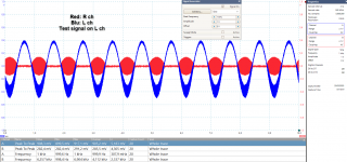
Digital oscilloscopes are handle little tools. I have a PC type (Picoscope 5444D). But I just experienced the under-sampled alias, and think this may be of interest. Most of us know about this digital limitation, but it is so easy to forget in the comfort of easy measurements. So this post is not about curing the oscillation, just to show how digital scopes can give bogus results.
So I fired up a new build, and of course instead of a fine and thin line the trace is wide and varies sporadically. Inserting a 1kHz test signal on the left ch gives weird bubbles on the right ch.
(This is a 6AS7 amp with a folded cascode input/gain stage. The measurements were with the output section not installed, only the input stage is active. The cascode transistors are 2SK1381, pretty fast devices, so no surprise regarding oscillations).
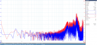
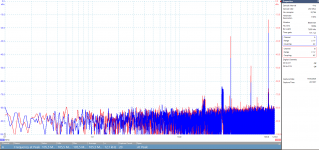
So I switched to FFT mode to pin point the oscillation frequency. The sample rate is 2x the max frequency selected for the FFT view. So if I select FFT to 100kHz, the sampling is 200ksps.
The FFT up to 100kHz shows a wide band (almost noise-ish) burst oscillation. Peak is 47kHz.
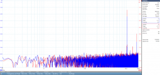
Increasing to 1MHz (992kHz really) FFT the peaks go up 323kHz and above, relatively wide band still. The sampling is now 1.984MSPS.
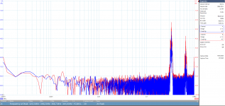
Going up to 8.929MHz, sample rate 17.86MSPS, the highest peak is at 1.75MHz.
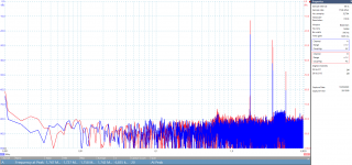
Up to 125MHz, sampling 250MSPS, the peak is 105MHz. There is some wide band peaking here and there.
The scope's max range is 250MHz, sampling 500MSPS. The peak is still at 105MHz, but it is not dead solid.
Obviously what I am seeing is under-sampling. The time domain view set to highest sample rate shows a relatively stable 104.8MHz but I suspect this is under-sampled and the actual oscillation frequency could be higher.
Are there any simple formulae that lets me calculate what the real frequency is based on the sample rate, and supposed frequency peaks shown at the given rate?
So now it's troubleshooting time...
Digital oscilloscopes are handle little tools. I have a PC type (Picoscope 5444D). But I just experienced the under-sampled alias, and think this may be of interest. Most of us know about this digital limitation, but it is so easy to forget in the comfort of easy measurements. So this post is not about curing the oscillation, just to show how digital scopes can give bogus results.
So I fired up a new build, and of course instead of a fine and thin line the trace is wide and varies sporadically. Inserting a 1kHz test signal on the left ch gives weird bubbles on the right ch.
(This is a 6AS7 amp with a folded cascode input/gain stage. The measurements were with the output section not installed, only the input stage is active. The cascode transistors are 2SK1381, pretty fast devices, so no surprise regarding oscillations).
So I switched to FFT mode to pin point the oscillation frequency. The sample rate is 2x the max frequency selected for the FFT view. So if I select FFT to 100kHz, the sampling is 200ksps.
The FFT up to 100kHz shows a wide band (almost noise-ish) burst oscillation. Peak is 47kHz.
Increasing to 1MHz (992kHz really) FFT the peaks go up 323kHz and above, relatively wide band still. The sampling is now 1.984MSPS.
Going up to 8.929MHz, sample rate 17.86MSPS, the highest peak is at 1.75MHz.
Up to 125MHz, sampling 250MSPS, the peak is 105MHz. There is some wide band peaking here and there.
The scope's max range is 250MHz, sampling 500MSPS. The peak is still at 105MHz, but it is not dead solid.
Obviously what I am seeing is under-sampling. The time domain view set to highest sample rate shows a relatively stable 104.8MHz but I suspect this is under-sampled and the actual oscillation frequency could be higher.
Are there any simple formulae that lets me calculate what the real frequency is based on the sample rate, and supposed frequency peaks shown at the given rate?
So now it's troubleshooting time...
Attachments
For instance the 105MHz signal (which is probably correct as the 'scopes front-end amp will roll off from 250MHz quite severely) = 6 * 17.86MHz - 1.75MHz
The undersampling spurs for a tone at frequency f will be at n*Fs +/- f, where n is an integer and Fs is the sampling rate, as sampling is like RF mixing. You would have to guess n though, so the best strategy is start at the fastest timebase setting and work down.
Expensive 'scopes do proper rate-conversion and don't show such under-sampling artifacts. This also gives you free sample-averaging to obtain higher ENOB. It takes quite a lot more hardware to do this though as digital filters are needed running at the full sample rate and various sub-multiples of it too. Other tricks you see are tracking the max and min samples so that you can see there's signal present even when its faster than the current timebase would display. Sometimes that's annoying though as it can just be HF noise.
With lots of memory depth this processing can be done off-line, as no realtime
processing needs to be done, other than filling memory - but then the refresh rate can be disappointing.
This is almost certainly due to:
insufficient filtering in your +250 power supply or
connecting the output to a too-low impedance. The load on 6SN7 cathode follower like this should not be lower than about 1,000 or 2,000 ohms. Check your power amplifier's input impedance.
a high resistance ground connection to the negative side of the power supply and the amplifier's input stage ground point. A preamp like this usually works best if its chassis ground point is as close as possible to the ground point on the input jack.
I have a stereo tube amp that I'd been working on plugged into a dual AFCI/GFCI outlet and it tripped a couple times indicating an arc fault. I assumed it was a nusance tripping but put a scope on the psu grounding and found out it was oscillating in ~10Mhz bursts on a 120Hz cadence  . It needed a gate stopper on a mosfet in a capacitance multiplier circuit in it. It had a very low level 120Hz buzzing sound in the speakers but it wasn't too objectionable. I'm not sure I would have caught the problem as quickly without the AFCI/GFCI tripping. I think a AFCI/GFCI outlet is a good idea with tube amps for safety and also for troubleshooting now.
. It needed a gate stopper on a mosfet in a capacitance multiplier circuit in it. It had a very low level 120Hz buzzing sound in the speakers but it wasn't too objectionable. I'm not sure I would have caught the problem as quickly without the AFCI/GFCI tripping. I think a AFCI/GFCI outlet is a good idea with tube amps for safety and also for troubleshooting now.
Last edited:
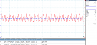
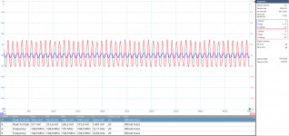
here is my square wave test. Any views on this would be helpful.
636p-dr parafeed, The 1khz squarewave looks the same from the plates as it does from the loaded transformer (same overshoot and minor ringing).
Gridstoppers on the pins (1k). Should i go chasing... or is this ok? The thickness of the horizontal is probe noise. I can flatten that out if i use short ground leads.
Last edited:
adamus,
Congratulations!
Your square wave response looks good to me.
Do not worry about the very small, very high frequency ringing.
Even bats do not hear 100kHz, and most tweeters do not go there either.
And . . . A Red Book 44.1k sample per second CD player with output filter does not have a fast enough rise-time to activate that ultra high frequency ringing.
Nyquist of 44.1k sample/sec is 22.05kHz, the frequency limit of a CD recording.
Change your Acquisition to Average, and watch the scope noise average out.
(if your scope has that feature).
Do not forget to set the Acquisition back to Sample, or to Peak, after the test (Sample is probably the scope default).
Last edited:
adamus,
You probably already know this, but some newbies do not.
The frequency response of a single pole low pass filter that has a Gaussian response is as follows:
0.35 / Rise Time = -3dB Bandwidth
Not all amplifiers have the 0.35 constant, but most are fairly close to that, so . . .
Example: An amplifier with a Rise Time of 10us
will have a -3dB bandwidth of approximately 0.35/10us = 35kHz.
The combined Rise Time of a square wave generator into an amplifier is as follows:
Root Sum Square of the two Rise Times
Example: Root (10us squared + 10us squared) = 14.14us combined rise time.
If the combined measured rise time is 3X longer than the generator rise time specification, for practical purposes you can take the amplifier rise time to be essentially the same as the combined measurement rise time result.
I bet your generator rise time is more than 3X faster than the amplifier rise time.
For a 50 Ohm output impedance generator like the one you have, always be sure to terminate the generator output with 50 Ohms (at the end of the cable that connects to the amplifier input).
That will preserve the generators rise time spec, and also its sine wave bandwidth spec.
(Do not terminate the generator at its output connector, terminate at the far end of the cable).
Technically for this to work properly to specification, the cable needs to be 50 Ohm impedance.
Last edited:
- Home
- Amplifiers
- Tubes / Valves
- Oscillation in tube amps