Common Coax Capacitance
As a general rule we can take common 50R coax such as RG8 & RG 58 as 30 pF/ft.
Similarly, common 75R coax such as RG9 & RG59 would be 20 pF/ft.
But dielectric failure is possible while used in the plate circuit of some of the tubes mentioned in this thread. For example, if the plate supply is 500V then 900V is a certainty on large signals while using pentodes or beam tubes. And more is possible running some kinds loudspeaker loads.
A better alternative would be braided shielding such as Belden 8669 or one of its relatives. In the distant past that is what some folks did. See the attachment from a 1940s RCA manual.
My own preference is to shield the low level wiring if need be. Then coax works OK. Use a White CF in the preamp to drive the input if you are concerned with HF audio rolloff.
Attachments
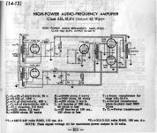
Thanks for that!In the distant past that is what some folks did. See the attachment from a 1940s RCA manual.
To me, there are some curious things in that schematic, such as C3 (main power supply filter cap) being located far away from the output transformer, and the B+ line between them being shown with electrostatic shielding. Normally we wouldn't expect (or want!) any signal voltages on the B+ rail, so why is it shielded?
Similarly, I don't understand why the ground line connecting the centre-tap of the interstage transformer is shown with shielding on it; why shield a wire that is grounded, i.e., has no signal on it?
-Gnobuddy
Those nodes are shielded because they have signal on them when input signal is applied, plus they have hum signal on them even with no signal. With low levels of bypassing, and loss of treble from screening input circuits, I think the aim is to minimise the local parasitic capacitance coupling from wiring in the amp to sensitive input stage.
The circuit uses 'back biasing' of the output 6L6's, so shielding on the IT CT makes sense. In those daze high capacity electrolytics were unknown, so Choke input filter was common, especially for large loads of great delta. You might have heard of the 'swinging choke', a choke of large inductance at small currents but much less under load. The advantage was small size for a given reduction in PS ripple & good voltage regulation. Not common now at all.
If I were to do this cct today I would add a low inductance cap of say 0.1 to 0.5 microF at the OPT HV CT to Common.
The large distance on the schematic separating the PS from the amplifier is nothing more than to make it easy to read. In the actual cct one can do whatever it takes to keep the strays to a minimum.
Thanks for that!
To me, there are some curious things in that schematic, such as C3 (main power supply filter cap) being located far away from the output transformer, and the B+ line between them being shown with electrostatic shielding. Normally we wouldn't expect (or want!) any signal voltages on the B+ rail, so why is it shielded?
any elyt cap suck hard above 20-30khz. more or less behaves like coil.
foil caps is a must, which i don´t see there.
That is part of what I was curious about. Some of the features of this particular schematic might be typical for that time period, while others might be specific to this particular circuit design itself, or the specific engineer who designed it.foil caps is a must, which i don´t see there.
Anyone know when it became normal to include smaller-value foil or ceramic caps in parallel with the main supply decoupling/filtering electrolytics? I've seen ceramic caps used like this in schematics from the 1960s, but I don't know about even earlier circuits.
-Gnobuddy
When did this become "normal"? Electrolytics maintain low impedance across the audio range - that is all that is needed. Therefore it is 'normal' for them not to need bypassing. Adding a small cap in parallel may create exactly the situation it is presumably intended to avoid: a high frequency peak in impedance. Fortunately most electrolytics have sufficiently high HF losses that the peak is not too big, so the unnecessary cap does less harm than it might.Gnobuddy said:Anyone know when it became normal to include smaller-value foil or ceramic caps in parallel with the main supply decoupling/filtering electrolytics?
So, people bypass electrolytics because they believe they are bad at HF and need it. The reality is that because electrolytics are not too great at HF they can damp down the resonance introduced by the extra cap. Normal quality electrolytics don't need bypassing; very low ESR electrolytics must not be bypassed!
And what about the fact that the vast majority of audio devices actually have bandwidths extending far beyond audio frequencies, and well into the RF range? Typical silicon epitaxial small-signal transistors have fT in the 150 MHz range; even a relatively ancient TL072 has a gain-bandwidth product of 3 MHz; and the small-signal vacuum tubes I'm using in my current DIY guitar amp project were originally designed to operate in UHF circuits (one datasheet states "...useful at frequencies up to 400 Mc".)Electrolytics maintain low impedance across the audio range - that is all that is needed.
Pretty much all the circuits I've seen - for decades now - from extremely credible sources (such as National Electronics, Analog Devices, Signetics, and other device manufacturers) specify the inclusion of small-value ceramic bypass caps, positioned close to the supply pins of the relevant devices.
-Gnobuddy
There is quite a bit of information on the web with regard to frequency dependence of electrolytic capacitors. Here is one of many-
impedance - Frequency dependence of electrolytic capacitors - Electrical Engineering Stack Exchange
impedance - Frequency dependence of electrolytic capacitors - Electrical Engineering Stack Exchange
The proper address for that link is- impedance - Frequency dependence of electrolytic capacitors - Electrical Engineering Stack Exchange
Here is a more complete reference, not required reading. And no test after this, but interesting just the same!
https://en.wikipedia.org/wiki/Electrolytic_capacitor
https://en.wikipedia.org/wiki/Electrolytic_capacitor
The forum is generally about valve amps - as is the thread - it's a red herring to point to high density pcb related circuits where the parts cost, and minimisation of footprint, and requirement for local bypassing of every IC due to pcb trace impedance, have dictated ceramic cap use in your example application.Pretty much all the circuits I've seen - for decades now - from extremely credible sources (such as National Electronics, Analog Devices, Signetics, and other device manufacturers) specify the inclusion of small-value ceramic bypass caps, positioned close to the supply pins of the relevant devices.
In an audio valve amp, the Williamson was the most onerous for high frequency response of the early amps, with frequency response test results going up to 1MHz even back in 1949 by Williamson himself. The high frequency response results helped to appreciate where parasitic performance could still introduce phase shifts that degrade stability margin at closed loop crossover which was up around 100-200kHz.
A radial electrolytic has a very broad and low impedance that is typically sustained well into the 100's of kHz before the impedance curve starts to rise from the minima region. Even when the impedance starts to rise, it is typically still a low value well beyond 1MHz, and so the device does its intended job as long as it is not inhibited by poor layout with long wiring connections to the relevant local circuit nodes.
Last edited:
That is a completely different situation to 'bypassing' PSU caps. Local bypass caps can be helpful, or even necessary. Routinely 'bypassing' big caps is unnecessary, and often unhelpful. I can understand why some people can't tell the difference between these two situations; those used to simulation believe that all wires have zero resistance and inductance and all loops have zero area.Gnobuddy said:Pretty much all the circuits I've seen - for decades now - from extremely credible sources (such as National Electronics, Analog Devices, Signetics, and other device manufacturers) specify the inclusion of small-value ceramic bypass caps, positioned close to the supply pins of the relevant devices.
There is nothing of any value in those references imho - perhaps if there is any salient data or information then that could be ascertained and summarised by the poster first.
My apologies, I did not realize that you are the arbiter of this thread. I assume you have read the entire Wiki article on caps & are now qualified to advise us. You have said that is your HONEST opinion. In which case you should run hard with that.
I also read quite a bit of the Wiki report & found it to be quite interesting. And others may have as well. Of those many are lurkers, not likely to share their opinions.
I, perhaps in error had assumed that DIY was a forum for the free exchange of ideas. Perhaps not!
For others who might be interested, over the past few days I’ve started three new threads covering some of the work I’ve done in this field. All tubes, some circuits perhaps not familiar to the regulars here.
And I do stand behind everything I’ve said in this thread related to Maxwell’s Equations, from power frequencies to microwave. I’ve done the work on paper & in hardware. But before I could get to the details I was shouted down. Not very democratic, at all!
 Everyone is entitled to have his/her own opinion, so let's try to keep the discussion civil and not let this forum become another r.a.t.
For the curious & others here are some capacitor resonances I checked 15 years ago.")
In addition to these examples two others come to mind. The 0.01 microF ceramic cap with 1/2 inch leads often used as the bypass cap in IF strip of tube type FM receivers is said to be series resonant at ~10 MHz. Often mentioned in the construction manuals of Heathkit, EICO & so on. I've not checked that but given their reputation I would have to believe.
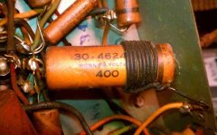
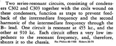
Another tubular is self resonant at 455 KHz, made by Philco. It looks like any other cap but could create serious problems in any audio amp. Refer to the attachment.
Some radio manufacturers did the same with an external coil on a common cap.
All this for information only.
Attachments
I also mentioned valves; specifically, one of the preamp valves I'm using, which the manufacturer rated for use up to 400 MHz. I'm using it at audio, but the device itself has sufficient bandwidth to be capable of oscillation at hundreds of megahertz.The forum is generally about valve amps - as is the thread - it's a red herring to point to high density pcb related circuits
The electrolytic capacitor data in one of the links jhstewart9 shows a roughly 2MHz impedance minimum for a 2.2 uF electrolytic capacitor. Since a number of other capacitor values are also plotted, one can compare them, and see that the impedance minimum seems to shift down in frequency by roughly a factor of 3 each time the capacitor value increases by an order of magnitude.
This suggests the frequency (of the impedance minimum) is inversely proportional to the square root of the capacitance; which is also mathematically plausible as this is how the resonant frequency of an LC circuit scales with the value of L or C.
Assuming that scaling relationship is reasonably correct, the 330 uF caps I use for B+ filtering in my preamp might be expected, very roughly, to have a resonant frequency in the range of 100 kHz. That is a factor of 4000 lower than the 400MHz capabilities of the valve itself.
It does not make any plausible engineering sense to me, to suggest that a capacitor that stops being a capacitor at 100 kHz, provides sufficient high-frequency bypassing for a 400 MHz-capable valve.
Now, to the issues of layout distances that were raised. When I used to build short-wave radio receivers as a teenager, I did everything I could to keep wire lengths to no more than, say, an inch; and that was at frequencies mostly below 20 MHz. I have once briefly worked with 600 MHz diode detectors, and at those frequencies, the advice I was given was to restrict wire lengths to no more than a millimetre.
With the large physical size of valves, and the necessity for adequate cooling airspace between them, it seems virtually impossible to keep lead lengths extremely short. Neither can one mount a big electrolytic cap right next to a valve, for the same heat and bulk related reasons.
Add in the 400 MHz capability of the 6AG5 valve I'm using, and, once again, I am forced to the conclusion that an electrolytic mounted, at a minimum, over an inch away, is not going to provide adequate supply decoupling to guarantee stability for my circuit.
What I'm getting from this entire discussion is that some valve circuitry may be sufficiently bandwidth-limited to get away with only electrolytic bypass caps on the power supply.
But I don't think that applies to all nominally audio-frequency valve circuitry. I shall continue to provide high-frequency bypassing local to any high-bandwidth valves I may use.
-Gnobuddy
Attachments
- Home
- Amplifiers
- Tubes / Valves
- Oscillation in tube amps