not sure if grid stoppers will stop oscilation, if opt behaves ugly in audio range.
(rule3, do not buy crap parts)")
Grid stoppers don't have anything to do with that. The reason to include them is to damp parasitic reactances that would otherwise lead to oscillation (either a parasitic Colpitts oscillator, or a negative resistance component of dirty admitances reflected back to the grid from the plate (Miller Effect)) of that one stage. Nothing to do with stabilizing a gNFB loop.
Cheap OPTs can have squirrelly phase characteristics at both ends of the audio spectrum that can make stabilizing a gNFB loop next ti impossible. They won't sound good anyway, feedback or no feedback.
No. It is the resistance which does the stopping job. Not by acting as a low pass filter with Miller capacitance
The Valve Wizard
ecc83+1k g.s. LPF ~820kHz
ecc88+1k g.s. LPF ~3,5MHz
ecc81+1k g.s. LPF ~2,5MHz
The PRIMARY reason for including a grid/gate/base stopper is to de-Q any parasitic LC circuits that would otherwise form a parasitic Colpitts oscillator, and/or to neutralize any negative resistances that might be reflected from dirty admittance in the plate circuit back to the grid.
That doesn't mean you can't make it do double duty, if the need arises.
""""" The PRIMARY reason for including a grid/gate/base stopper is to de-Q any parasitic LC circuits that would otherwise form a parasitic Colpitts oscillator, and/or to neutralize any negative resistances that might be reflected from dirty admittance in the plate circuit back to the grid. """""
"""""" The primary function of a grid stopper is to add sufficient loss to any accidental resonator (or, equivalently, to overcome the negative resistance at a valve port due to parasitic effects) in order to ensure that there is insufficient loop gain for parasitic oscillation.""""""
I think that the tubes which we use in audio ( like ECC81 , 83 e.t.c ) and the circuits we usually use in audio ( most of them are Common Cathode Circuits ) do not suffer from all this effect , I mean that those tubes - circuits will have something like self neutralizing in the range of the very high frequencies , exactly because their miller capacitance ( dominate ) prohobit them from doing such things by providing a short path to the ground , I believe that your sugestions will find more place in common grid , pentodes and cascodes circuits ! .
""""" A secondary function (except in guitar amps) is to form a low pass filter with Miller capacitance; this secondary function can be a nuisance as it adds phase shift and so can make feedback loop oscillation more likely . """"""
As for the feedback loop oscillation , we can solve it by some compensation ! .
It's quite true that in many vintage implementations grid stoppers were not used with triodes having relatively low transconductance aka the usual 12xx7 series dual triodes. In many instances however lead dress seems to have been somewhat critical, and when building kits as a youngster I carefully followed the recommended layouts in the p2p kits I built.
Many years later as I developed my first phono stage design from scratch I made a test breadboard using 12AX7As and found out the importance of stopper resistors in that application. I have somewhat indiscriminately used them since, however in certain applications like phono stages they do have a downside and that is in terms of noise, a 1K grid stopper may introduce as much or more thermal noise than the winding resistance of the cartridge you are using. In such cases I like to use 47 - 220 ohm resistors, making note that I use high transconductance VHF triodes like the 5842/417A and 6S3P in my phono stage designs - without stoppers even with good layout they will likely oscillate.
Many years later as I developed my first phono stage design from scratch I made a test breadboard using 12AX7As and found out the importance of stopper resistors in that application. I have somewhat indiscriminately used them since, however in certain applications like phono stages they do have a downside and that is in terms of noise, a 1K grid stopper may introduce as much or more thermal noise than the winding resistance of the cartridge you are using. In such cases I like to use 47 - 220 ohm resistors, making note that I use high transconductance VHF triodes like the 5842/417A and 6S3P in my phono stage designs - without stoppers even with good layout they will likely oscillate.
ECC81/12AT7 was developed as a VHF valve, so may need grid stoppers. ECC83/12AX7 has low gm so probably has less need of them. ECC82/12AU7 was developed from a VHF power triode so may need stoppers.Dimitris AR said:I think that the tubes which we use in audio ( like ECC81 , 83 e.t.c ) and the circuits we usually use in audio ( most of them are Common Cathode Circuits ) do not suffer from all this effect
No. The place you are most likely to see grid stoppers is grounded cathode stages. Miller capacitance adds a capacitance to ground, not a resistance. A capacitor does not damp parasitic oscillation, but merely changes the frequency.circuits will have something like self neutralizing in the range of the very high frequencies , exactly because their miller capacitance ( dominate ) prohobit them from doing such things by providing a short path to the ground , I believe that your sugestions will find more place in common grid , pentodes and cascodes circuits ! .
Compensation may be unnecessary if the forward path is properly designed. Guitar amps can get away with their huge grid stopper values because they typically use much less feedback than hi-fi.As for the feedback loop oscillation , we can solve it by some compensation ! .
Surely this thread should be about sharing wisdom in solving oscillation problems, not sharing confusion about oscillation?
ECC81/12AT7 was developed as a VHF valve, so may need grid stoppers. ECC83/12AX7 has low gm so probably has less need of them. ECC82/12AU7 was developed from a VHF power triode so may need stoppers.
I didn't say to omite grid stoppers at all , I usually use 1K in all my circuits either it is a line preamp or RIAA preamp or Power amp , even with ECC83 and with ECC85 ( which is closer to ECC81 ) the same thing 1K grid stopper , the reason is better to be sure , only in one line preamp with the PCF200 I use 5K6 because of it's pentode high transconductance ! . And I see you say may need this means that you are not sure ! ( but you will be sure if you do it in practice ) .
""""""No. The place you are most likely to see grid stoppers is grounded cathode stages. Miller capacitance adds a capacitance to ground, not a resistance. A capacitor does not damp parasitic oscillation, but merely changes the frequency. """""""
Miller capacitance adds a capacitance to ground , yes , but this capacitance has very low impedance in VHF , so it will act like a short circuit for those frequencies ! .
"""""" Compensation may be unnecessary if the forward path is properly designed. Guitar amps can get away with their huge grid stopper values because they typically use much less feedback than hi-fi."""""
I know it , for example if we have a line preamp , which have very low phase shift from it's input to it's output then we can use more feedback without the risk of oscillation ( I said it in other post in this thread ) , beside this , every circuit that I build I test it in the oscilloscope , not with 10KHz or 20KHz square wave , but with 100KHz SQ , so if there is any oscillation will be seen , then I choose the right amount of compensation ! , as you see we have to be practical too not only theoritical and not to " blame " the others for confusion ! .
""""""" Surely this thread should be about sharing wisdom in solving oscillation problems, not sharing confusion about oscillation? """""
Last edited:
<Snip>
Miller capacitance adds a capacitance to ground , yes , but this capacitance has very low impedance in VHF , so it will act like a short circuit for those frequencies ! .
<snip>
No, this isn't entirely correct. Miller capacitance refers specifically to cgp when multiplied by the effective mu of the tube in question. Grid circuit wiring inductance and capacitance from grid to ground can create a situation where you end up with enough grid circuit phase shift to make an oscillator, usually this is somewhere in the RF to VHF region. In some instances if levels are low enough you may not even be aware of the fact that the stage is oscillating.
Parasitic oscillation depends on both the valve and the circuit, including physical layout. Therefore it does not always occur. Therefore a particular valve may or may not need stoppers. As always, contex is everything. My "not sure" is not an expression of ignorance about electronics, but an expression of ignorance about whatever circuits/layouts (good or bad) people may use.Dimitris AR said:And I see you say may need this means that you are not sure ! ( but you will be sure if you do it in practice ) .
It is not as simple as that. Transit time etc. can add negative resistance too.Miller capacitance adds a capacitance to ground , yes , but this capacitance has very low impedance in VHF , so it will act like a short circuit for those frequencies ! .
Hi,
Hoping to get some fresh ideas on how to tackle this. I have an oscillation around the LTP phase inverter. For those that don't know the panel covering the back of the chassis and amplifier has a thin layer of aluminum that is most likely intended as a Faraday shield. It is known that there is an oscillation in these amps at the PI but when the ribbon connector is in close enough proximity to the shielding it creates enough parasitic capacitance to mitigate it. In the case with the current amp I have it's still slightly visible with the back panel on, and in use certain conditions arise to get the whole thing out of control. There has been several methods that are floating around to fix this, I will provide a link with the most common methods.
I know there are some brilliant people lurking in these waters that might help come up with a better solution to fix the oscillation and or find out where it is coming from. Personally I think it's a combination of bad solder connections and the wiring, vibrating the amp causes it to go in a fit. I want to remove the ribbon connectors and use a more normal wiring approach and see if it goes away.
Since the PI is where the FB loop is inserted from the secondary of the output transformer I wonder if this is part of the problem.
I plan on hooking it back up later and sniff out the issue, maybe we can also get some fresh eyes on this from you gentlemen.
Original thread in MI section: http://www.diyaudio.com/forums/instruments-amps/290699-sovtek-el84m.html
BillM's page on the matter: Cream Board Phase Inverter Oscillation – Billm Audio
Schematic is on page 2, rev. A: http://support.fender.com/schematics/guitar_amplifiers/Blues_Junior_schematic.pdf
Last edited:
Running long cables to the valves is basically a bad idea. Given such a poor physical layout, it is hardly surprising that there are stability problems. As capacitive coupling seems to be the issue one thing to try is adding a grounded conductor between the cable and whatever is coupling to it. This need not be a solid conductor; a zigzag of stiff wire may do. It can be grounded to either the chassis or signal ground, whichever is most convenient.
Hi, yes this design and layout is pretty bad. The grid stop resistors aren't even on the boards that the sockets are on, they are on the main board connected via about 5" of ribbon cable.
I am not too sure what you mean when you say "between the cable and whatever is coupling to it". Are you saying replace the ribbon cable with shielded cable and shield the cable to earth? Or, wrap a wire around the ribbon cable and connect it to earth?
Is this a case of capacitive coupling causing the oscillation and also capacitive coupling fixing the problem?
As capacitive coupling seems to be the issue one thing to try is adding a grounded conductor between the cable and whatever is coupling to it. This need not be a solid conductor; a zigzag of stiff wire may do. It can be grounded to either the chassis or signal ground, whichever is most convenient.
I am not too sure what you mean when you say "between the cable and whatever is coupling to it". Are you saying replace the ribbon cable with shielded cable and shield the cable to earth? Or, wrap a wire around the ribbon cable and connect it to earth?
Is this a case of capacitive coupling causing the oscillation and also capacitive coupling fixing the problem?
Grid circuit wiring inductance and capacitance from grid to ground can create a situation where you end up with enough grid circuit phase shift to make an oscillator, usually this is somewhere in the RF to VHF region. In some instances if levels are low enough you may not even be aware of the fact that the stage is oscillating.
I think that if the grid stopper resistor will placed very close to the socket of the tube , then we get rid of the grid circuit wiring inductance ( good layout rules ) , but we will still have other " parasitic " inductances ! .
Something in the circuit is capacitively coupling to the ribbon cable - that is why moving the ribbon affects the oscillation. To reduce this unwanted coupling you need to put a grounded conductor between them. Don't fully shield the ribbon, as that will introduce extra capacitance and could cause new problems. Don't wrap a wire around the ribbon, as that will have a similar effect. Just try to identify what the ribbon is coupling to, then put something grounded between them so the ribbon can't 'see' the other circuit node, or at least can't see it very well. Look for something in the circuit (physically nearby) with the same polarity signal but at a greater amplitude. Or antiphase polarity (when phase shift is finishing the job).famousmockingbird said:I am not too sure what you mean when you say "between the cable and whatever is coupling to it". Are you saying replace the ribbon cable with shielded cable and shield the cable to earth? Or, wrap a wire around the ribbon cable and connect it to earth?
I had to do this with my Mullard 5-20 amp. A large polypropylene coupling cap was causing oscillation so I put a zigzag of grounded wire between it and the LTP output. Note that an LTP has both polarities at its output, so it is always possible for one of them to create problems via capacitve coupling to an earlier point in the circuit.
Something in the circuit is capacitively coupling to the ribbon cable - that is why moving the ribbon affects the oscillation. To reduce this unwanted coupling you need to put a grounded conductor between them. Don't fully shield the ribbon, as that will introduce extra capacitance and could cause new problems. Don't wrap a wire around the ribbon, as that will have a similar effect. Just try to identify what the ribbon is coupling to, then put something grounded between them so the ribbon can't 'see' the other circuit node, or at least can't see it very well. Look for something in the circuit (physically nearby) with the same polarity signal but at a greater amplitude. Or antiphase polarity (when phase shift is finishing the job).
I had to do this with my Mullard 5-20 amp. A large polypropylene coupling cap was causing oscillation so I put a zigzag of grounded wire between it and the LTP output. Note that an LTP has both polarities at its output, so it is always possible for one of them to create problems via capacitve coupling to an earlier point in the circuit.
Thank you for clarifying for me. I have some more time today to work on the amp, my first course of action is to make a zig zag ground wire and place it physically on once side of the ribbon cable or the other. When the back panel of the amp is off there is nothing on that side of the ribbon cable to couple to, but this is when the oscillation is at it's worst. So maybe the ribbon cable is coupling to something on the main board? But then why does it get better when the back panel is put back on? From what I can extrapolate from the linked article, a guy in oz says that there is a resonance in the PI from capacitance and resistance?
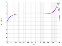
I think he meant to say inductance? That page makes me feel that they are just guessing at fixes and haven't actually found the exact problem. Oh well I am going to make zig zag wire and report back with my results. I actually do feel this is a better approach now that I think about it. I am still going to resolder the ribbon connectors, I don't trust the wave solder machine. For your amusement, I am re-posting some screen-shots of a pair of ultra-expensive and highly regarded "tube line amplifiers" with problems.
Hi, and wow! Is there a transformer in the line amp signal path?
Hi, and wow! Is there a transformer in the line amp signal path?
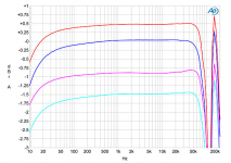
You guessed it. (FYI, the SYS2722 load is 100k||100pf.) A little bit of a snubber on the output transformer missing.
Here are a couple more.
Attachments
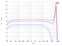
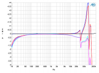
A little bit of a snubber on the output transformer missing.
I'd say so
Maybe they were hoping it would be plugged into a lower impedance load, possibly 10k is enough to dampen the resonance? Do they also happen to sell such power amps?
- Home
- Amplifiers
- Tubes / Valves
- Oscillation in tube amps