Hello folks ")
I have hesitaded a bit to present this building because of all the competing yardsticks and so forth...
But because this is the worlds most visited place for DIY works I had to take a chance
I want to share my design and I also accept all the criticism I can get. Thats the rules, I know.
I Also want to share because I think this is the best forum out there, there is.
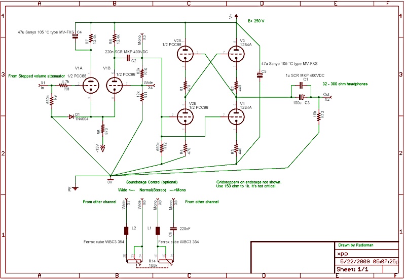
This is the shcematic of the amplifier:
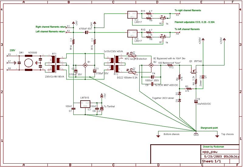
This is the schematic of the PSU:
The story of this amp is on one of my homepage sites:
Ove's XPP OTL HeadPhoneAmp
I would be glad for any comments
I have hesitaded a bit to present this building because of all the competing yardsticks and so forth...
But because this is the worlds most visited place for DIY works I had to take a chance
I want to share my design and I also accept all the criticism I can get. Thats the rules, I know.
I Also want to share because I think this is the best forum out there, there is.
This is the shcematic of the amplifier:
This is the schematic of the PSU:
The story of this amp is on one of my homepage sites:
Ove's XPP OTL HeadPhoneAmp
I would be glad for any comments


What have I done wrong?
Hi all
It's summer and I have a low profile with electronics.
Anyway, there must be some problem with my languish or my delivery of this project..
Please tell me if my languish are to bold or if you see the advertising for my small "at the side " company... which is in it's infancy ( not cashing any money at all ) or any thing else that I, with my poor english isn't aware of..
I think this is a very good project, at no cost, for an intermediate DIY audio addict to test.
Sincerely // Ove
Quick rundown
Hi all and thanks for looking.
A quicky before you go in deapth reading the links I refer to
It has no output transformer.
The endstage is symmetrically built, X push pull Class A. The more load the less distortion is significant for this amplifier.
The use of common cathode amplifier as the gain/front stage is overlooked. Gives low distortion and very high bandwith.
No global feedback, just some small local feedback at the frontstage, where the smart option to also have a "soundstage control" resides.
Easy to build PSU. Gives very clean stabilized Voltage without any large iron and inductances (big coils).
No special "boutique" components. Instead rather inexpensive and readily available components, including the tubes, allthough the PCC88 is beginning to be more pricey lately.
This amplifier has actually been built exactly as the schematic on my homepage. I'm actually using it in the livingroom to my own delight.
Gordy said:The project looks interesting. How much power into 30 Ohm 'phones?
I havent measured that because I mainly use 60 ohm or 300 ohm. I have a pair of 32 ohm Sennheizers though, that I have used to test with and they give more then enough for any ear
It's also possible to tweak out more current if necessary out of this design, if you allways run it with really low loads. Or parallell more 12B4's to drive even speakers ... in a very inefficient way though
ikoflexer said:Hi, what is the approximate current drawn by each channel?
60mA
10ma in each common cathode triodes and 10mA trough the two PCC88 endstage triodes and the last two 12B4's takes 30mA.
Thanks Ove for the insight on your amplifier! With your explanation the schematic is quite comprehensible...
As I said my electronic education is zero, but bitten by the tube bug I have started to build headphone amplifiers at a rate of about one per year...
I am at number 6 now with the best being an Aikido with parafeed output transformers and fully regulated supplies (HV courtesy of Salas).
Saying that your design could also be used with parafeed opt's... like the inexpensive Hammond 119DA that are giving me very good results so far. From my (still limited) personal experience I don't like big electrolytics as output too much...
I will put your schematic on my future projects list
- Status
- This old topic is closed. If you want to reopen this topic, contact a moderator using the "Report Post" button.
- Home
- Amplifiers
- Tubes / Valves
- My XPP OTL Headphoneamp