for all you horizontal deflection fans...
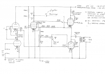
based on http://home.alphalink.com.au:80/~cambie/6AN8amp/Grant_Wills_6CM5amp.htm but with obviously different pre and splitter.
As usual, based on stuff I have and with a serious buget limitation in mind. Semiconductors and passives total round $30, the valves owe me about NZ$4 each, and the OPTs were NZ$30. Transformers are ex-surplus affairs at a total of NZ$20.
THe PTX is a multi-tapped item providing up to 250vac @ 150ma. THe heater TX is able to supply around 28v @ 4A, so the heaters will be series connected - all outputs on one series, inputs and splitters on another. Total current draw will be around 1.6A - plenty of headroom, but am I opening up to crosstalk between channels?
Now, I reckon to get around 130v p-p out of the 6J7 with a 2Vrms input, but would appreciate guidance. I understand this converts to only 65v p-p at each of the splitter outputs, hence the MOSFET follies inspired followers to take the load to the EL36 grids.
I recall Tubelab discussing MOSFET followers and recomending +/- 100V supply, so thats that explained. THe various bias supplies are self-explanatory. THe start delay would appreciate a practised eye.
Question on feedback - the original circuit has a gfb circuit from the OPT to the input valve cathode. Since I am using LEDs to provide the bias on the input valve, can I still use the divider network to provide feedback?
Attachments
Hi aardvarkash10,
No, you cannot.
Regarding the MOSFET drivers: There is no need for them when running the EL36 in BPT mode like you do. As a matter of fact they even wouldn´t be strictly needed when triode-strapping the EL36, since its CMiller will be comparatively lowish due to the lowish µ.
Regards,
Tom
Question on feedback - the original circuit has a gfb circuit from the OPT to the input valve cathode. Since I am using LEDs to provide the bias on the input valve, can I still use the divider network to provide feedback?
No, you cannot.
Regarding the MOSFET drivers: There is no need for them when running the EL36 in BPT mode like you do. As a matter of fact they even wouldn´t be strictly needed when triode-strapping the EL36, since its CMiller will be comparatively lowish due to the lowish µ.
Regards,
Tom
I just built PP Triode EL86 with an E180CC direct coupled to a 6N6P in
a concertina style splitter, cap coupled to outputs run cathode biased
wth 285v on the plates (20v on cathodes) and 45ma per tube.
No problem here driving these things, there not difficult tubes to drive.
--------
Posted at the same time as Tom, he's right no need for such a drive.
a concertina style splitter, cap coupled to outputs run cathode biased
wth 285v on the plates (20v on cathodes) and 45ma per tube.
No problem here driving these things, there not difficult tubes to drive.
--------
Posted at the same time as Tom, he's right no need for such a drive.
aardvarkash10 said:
. . .
Question on feedback - the original circuit has a gfb circuit from the OPT to the input valve cathode. Since I am using LEDs to provide the bias on the input valve, can I still use the divider network to provide feedback?
Sure, you can !
Just insert a small (10 to 100 Ohms) resistor between the cathode of the LED and the ground and return here some voltage from the OPT secondary from another resistor.
Then you have the divider network.
To void ground loop, ground the other end of this secondary at the ground point of the inserted resistor, not elsewere.
Yves.
OK, got this one finished a couple of weeks ago and couldn't wait for the pre-amp that I'm building to get it up and running so a quikndirty passive (dual 50k log pot and a couple of RCA sockets!) had it running last night. Source a Philips DVD playing CDs, speakers a REALLY inefficient Wharfdale passive sub with home-built 4 inch speakers.
Colour me happy.
Subjective testing only, more than sufficient power, no obvious aural flat spots or peaks although PERHAPS a little bright/trebley to my ear, very slight hum at the speaker with no signal, but disappears immediately (or becomes unoticeable) when any level of signal starts. The hum is the only thing I could measure and it is 1mv at the speaker termination using a DVM.
No feedback in the build so far apart from the u/l connection. I may try a little gNFB in it after some listening.
Question for the tehno-types. What should i measure to ensure its as good as can be? I have a small, elderly single channel 5mhz o/scope (Trio) and experience at low voltages as an auto-electrician using a 'scope, but I get a little uncertain of myself when trying to get measurements that then need interpreting. Some assistance here would be good.
For the asthetes - its in a solid rimu (NZ native timber) plinth and aluminium top plate with the terminations on an ali channel across the back. I rekon it looks good and it has the WAF Seal of Approval.
For the asthetes - its in a solid rimu (NZ native timber) plinth and aluminium top plate with the terminations on an ali channel across the back. I rekon it looks good and it has the WAF Seal of Approval.
We have some furniture made from RIMU with brushed anodized alum it looks great
thanks cj - perhaps I should do the next in ironbark or eculyptus? ")
Having listened for a few days, its DEFINITELY harsh in the upper registers - I may need to revisit the coupling caps and move them up from my el-cheapo 0.1uf items.
Starts to distort fairly early on too - unsure what hte cause of this is so in hte absence of any educated input here, I'll dive on in with a scope and a copy of a 1960's treatise on the use thereof gleaned from the Millett library.
Mrs Aardvark will be gutted - she only just got used to having the amp produce noise and will not understand further "faffing about".
OK, so it s a few days later and not a lot has happened due to having to reconfigure the "entertainment unit" to accept the new amp etc. This involved endless hours of fun with a router and table saw, square metres of MDF and some PVA glue. True to form, it remains unpainted, but at least the glowey bits and the roundy round bit are out of the clutches of the autistic 12 year old...
I digress.
The 6CM5s sounded kinda ok, but I haven't had the space to lift its skirts again and suss out why it sounds like it does. Next best fiddle around? Tube rolling of course!
And just by good luck, I have 16 x 6DQ6B tubes which, saints be praised, are the same pin-out as the 'cm5!
Plugged them in, no change to bias, no change to anything... They sound better! Noticably lower output, but muuuuuch smoother. Some of the 'DQ6B's I have are RCA some are AWA - the RCAs have a smaller plate. Didn't notice any clear difference in sound between the two.
So, the 'DQ6B's are staying in the amp and I will take a look at rebiasing as well as all the other stuff.
Except now I need another amp to replace this one so I can fiddle without the family whining on about the lack of sounds. Good excuse to build a new amp eh... now, where ARE those transformers I took from the AMI jukebox?
yep - a Murray is on the list! I've been discussing this briefly with Phil Wait in Australia since he and Wim are the only people I know who have built Murrays recently. The 550V B+ is a little daunting but you have to go there some time.
Dilemma is that i have all the bits for a pp unit needing 6.6k transformers (got 6 of these out of salvaged jukeboxes), I have 807s, EL36s, the 6DQ6s, 1625s as output tube options (along with a number of EL84s). As you can see, I'm kinda addicted to top caps!
Next build will be EITHER Murray using EL36 and / or possibly the 6DQ6s, OR a relatively straightforward 807 pp using the 6.6k OPTs.
Of course, a straight parafed SE using the 1625s, toroidal OPTs CCS loaded would be fun... aaaaaaargh!
Tom will be by any time soon to recommend trioding any of these options... Respec' Tom! But except for the 1625 SE, horsepower is the name of the game with these - my speakers (and any I'm likely to own or use) are not sensitive enough for triode outputs.
Last edited:
- Status
- This old topic is closed. If you want to reopen this topic, contact a moderator using the "Report Post" button.
- Home
- Amplifiers
- Tubes / Valves
- EL36/6CM5 pp design critique