Hi,
I'm trying to come up with a power supply for the JE Labs/Angela 2A3 SE amp. I want to build the 6SL7 SRPP version, but as a stereo amp on a single chassis. Schematic:
I've tried to model the power supply in PSUD, and it checks out for monoblock construction. The photos after the schematic seem to indicate a stereo amp though, and I don't understand how this power supply can provide those voltages for a stereo amp.
http://www.angela.com/catalog/how-to/EZ.2A3.html
And the page for the non-SRPP version which describes the amp in more detail:
http://www.angela.com/catalog/how-to/SE.2A3.html
Also, here's the power supply I'm trying to work on (that will be the image at the end, as I need to upload it). Here's what I'm trying to do:
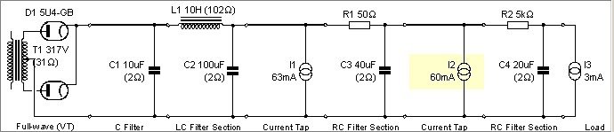
* Use a common CLC section, followed by RCRC sections for each channel. The 2A3 connects after the first RC, and the 6SL7 after the second RC.
* A 2A3 is roughly 60mA, and a 6SL7 is 2-3 mA. Since I can't think of a way to model parallel power supplies, I put in I1 which is a 63mA current sink after the CLC section, this models the other channel. I2 and I3 model the 2A3 and 6SL7 respectively. The transformer is 300V ct, and someone told me to adjust for 120/115 because Hammond transformers are designed for 115V line voltage.
Does this seem OK so far?
* When I did that with the original PS schematics, the voltages didn't end up where they should. So either I'm doing something wrong here, or this amp was designed to be a monoblock, but there are two filament transformers.
* Anyway... any comments and/or advice on my power supply? Feel free to be brutal if necessary")
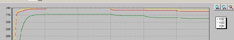
* I guess stepped current loads can be used to see how the circuit behaves under dynamic conditions, right? So, how much should I increase the current by? I used around 10% increase, at 3, 4, and 5 seconds for the different current sinks. Is this a reasonable figure to use? How much voltage sag is acceptable, and how quickly should it settle down? I know that ideally both the difference and the time delay should be as small as possible, but I don't have any idea of what a good ballpark figure is.
* As you can see (thought not very well), the voltage on the 2A3 seems to recover fairly quickly, but the 6SL7 voltage takes almost a second to stabilise.
That's all I have so far. Please let me know if this is mostly on the right track. And please suggest any changes you might feel appropriate. I'm trying to stay away from the GZ37 in the original schematic, because all the ones I find seem to be pretty expensive.
Thanks,
Saurav
My PS so far:
I'm trying to come up with a power supply for the JE Labs/Angela 2A3 SE amp. I want to build the 6SL7 SRPP version, but as a stereo amp on a single chassis. Schematic:
An externally hosted image should be here but it was not working when we last tested it.
An externally hosted image should be here but it was not working when we last tested it.
I've tried to model the power supply in PSUD, and it checks out for monoblock construction. The photos after the schematic seem to indicate a stereo amp though, and I don't understand how this power supply can provide those voltages for a stereo amp.
http://www.angela.com/catalog/how-to/EZ.2A3.html
And the page for the non-SRPP version which describes the amp in more detail:
http://www.angela.com/catalog/how-to/SE.2A3.html
Also, here's the power supply I'm trying to work on (that will be the image at the end, as I need to upload it). Here's what I'm trying to do:
* Use a common CLC section, followed by RCRC sections for each channel. The 2A3 connects after the first RC, and the 6SL7 after the second RC.
* A 2A3 is roughly 60mA, and a 6SL7 is 2-3 mA. Since I can't think of a way to model parallel power supplies, I put in I1 which is a 63mA current sink after the CLC section, this models the other channel. I2 and I3 model the 2A3 and 6SL7 respectively. The transformer is 300V ct, and someone told me to adjust for 120/115 because Hammond transformers are designed for 115V line voltage.
Does this seem OK so far?
* When I did that with the original PS schematics, the voltages didn't end up where they should. So either I'm doing something wrong here, or this amp was designed to be a monoblock, but there are two filament transformers.
* Anyway... any comments and/or advice on my power supply? Feel free to be brutal if necessary
* I guess stepped current loads can be used to see how the circuit behaves under dynamic conditions, right? So, how much should I increase the current by? I used around 10% increase, at 3, 4, and 5 seconds for the different current sinks. Is this a reasonable figure to use? How much voltage sag is acceptable, and how quickly should it settle down? I know that ideally both the difference and the time delay should be as small as possible, but I don't have any idea of what a good ballpark figure is.
* As you can see (thought not very well), the voltage on the 2A3 seems to recover fairly quickly, but the 6SL7 voltage takes almost a second to stabilise.
That's all I have so far. Please let me know if this is mostly on the right track. And please suggest any changes you might feel appropriate. I'm trying to stay away from the GZ37 in the original schematic, because all the ones I find seem to be pretty expensive.
Thanks,
Saurav
My PS so far:
Attachments
saurav, hi there
like you, i used PSUD to model the PSU for the JE Labs SRPP 2A3.
please allow some tolerances for the PSUD software.
if your 2A3's are connected on C3, there should be no current tap I1
look here for some ideas on stereo power supply
like you, i used PSUD to model the PSU for the JE Labs SRPP 2A3.
please allow some tolerances for the PSUD software.
if your 2A3's are connected on C3, there should be no current tap I1
look here for some ideas on stereo power supply
An externally hosted image should be here but it was not working when we last tested it.
if your 2A3's are connected on C3, there should be no current tap I1
The 2A3 for one channel connects at C3, and so I thought I1 would model the current draw of the other channel, which would split off after the CLC section. Is that incorrect? If so, could you please explain why?
Thanks,
Saurav
Hi Saurav;
I used PSUD II to model my JE Labs 2A3 (2001 ed) power supply, and all I did was to use 125mA as the current draw for the 2A3's (actually I cheated even more and just assigned an arbitrary 130mA or so for the whole kit and kaboodle, ignoring the decoupling caps to the input stage! ).
FWIW, using a Hammond 272JX-->RCA 5U4GB-->20uF Sprague Atom-->10H Hammond 193M-->100uF Sprague Atom I get about 345VDC to the 2A3's. With a 5AR4, it's about 30V higher IIRC. I'm only using a single "CRC" for the 2A3's, and paralleled "RC's" for the 6SL7's. If you use something other than the recommended GZ37, you will need to delay the B+ in some way. You might consider the 5AR4 - SovTek's worked fine in mine with a dropper resistor, but I had a bunch of NOS RCA 5U4GB's lying around so....
On the subject of the 120V/115V thing, there's one other thing to consider, and that's your filaments. It's been my experience that Hammonds tend to run the filaments a little hot because of this, so IMHO you should check the voltages on 'em and if they're more than a few percent high, think about dropper resistors - or if you're feeling ambitious you could always go DC and add a regulator to the filament supply.....
Good luck!!
Morse
I used PSUD II to model my JE Labs 2A3 (2001 ed) power supply, and all I did was to use 125mA as the current draw for the 2A3's (actually I cheated even more and just assigned an arbitrary 130mA or so for the whole kit and kaboodle, ignoring the decoupling caps to the input stage!
).FWIW, using a Hammond 272JX-->RCA 5U4GB-->20uF Sprague Atom-->10H Hammond 193M-->100uF Sprague Atom I get about 345VDC to the 2A3's. With a 5AR4, it's about 30V higher IIRC. I'm only using a single "CRC" for the 2A3's, and paralleled "RC's" for the 6SL7's. If you use something other than the recommended GZ37, you will need to delay the B+ in some way. You might consider the 5AR4 - SovTek's worked fine in mine with a dropper resistor, but I had a bunch of NOS RCA 5U4GB's lying around so....
On the subject of the 120V/115V thing, there's one other thing to consider, and that's your filaments. It's been my experience that Hammonds tend to run the filaments a little hot because of this, so IMHO you should check the voltages on 'em and if they're more than a few percent high, think about dropper resistors - or if you're feeling ambitious you could always go DC and add a regulator to the filament supply.....
Good luck!!
Morse
saurav, i see - that's where the fork starts (split)
hmmm, i modeled on the PSUD like what morse did, in my case (you still have the link to my schematic do you)
morse, thank you for emphasizing my oversight of not warning saurav about that (the filaments)... and on that note, i was thinking that this scheme will always have 110V for the filament. can you please check?
Example:
(The label primary should have said, secondary)
using the 300 series of hammond wired for 220V, and a filament transformer with 110V primary...
i'll tap the filament 110V primary to the 3XX 110V primary, to have 110V always regardless of the 3XX primary voltage, which in this example is 220V.
is this sound or crazy
hmmm, i modeled on the PSUD like what morse did, in my case (you still have the link to my schematic do you)
morse, thank you for emphasizing my oversight of not warning saurav about that (the filaments)... and on that note, i was thinking that this scheme will always have 110V for the filament. can you please check?
Example:
An externally hosted image should be here but it was not working when we last tested it.
(The label primary should have said, secondary)
using the 300 series of hammond wired for 220V, and a filament transformer with 110V primary...
i'll tap the filament 110V primary to the 3XX 110V primary, to have 110V always regardless of the 3XX primary voltage, which in this example is 220V.
is this sound or crazy
Is this sound or crazy
Crazy, I'm afraid. The transformer does not regulate, it simply ratios voltages by its turns ratio. 220V to 110V simply means a ratio of 2:1, so if the 220V going in rises by 5%, then the 110V out will also rise by 5%.
If you are really worried about heater voltages, the best thing to do is to use regulated DC.
My experience is that PSUD tends to predict slightly low voltages (only a few percent).
So then if I have a constant (regulated) 220V, I get 110V on the filament transformer primary while connected to the power transformer 110V tap.Crazy, I'm afraid. The transformer does not regulate, it simply ratios voltages by its turns ratio. 220V to 110V simply means a ratio of 2:1, so if the 220V going in rises by 5%, then the 110V out will also rise by 5%.
Not bad for my intentions, which is to run my amp on 220V (currently wired for 110V) even if my filament transformer primaries are 110V.
Thanks. I hope I'm not missing anything else.
saurav,
do you mean to remove the 27K and 20uF on the amp circuit (which i consider as still part of the PSU) and tap the upper 6SL7 plate directly as I3? Is that the objective of your R2 and C4 in the PSUD?
arnoldc said:I hope I'm not missing anything else.
There's no problem with using the primary of a transformer as an autotransformer, but you will have to derate its secondaries accordingly. Thus, if the heater transformer takes a load of 100VA and the total rating of the other transformer is 200VA, you will have to derate its secondaries to 100VA. Actually, since transformers are not 100% efficient, you will have to derate it to less than that.
It's a shame to %&$ on your firework, but I don't think this is a terribly good idea.
Thanks for all the responses.
Hmm, I hadn't really thought about that. So a 5AR4 has a ramped up B+? This is the difference between directly heated vs. indirectly heated diodes, right?
Yes, I had that at the back of my mind.
Probably at a later "what else can I do to this" stage.
That's what I was thinking - C4 is 20uF, and change 27K to 5K. If I do that though, I'll need to put a resistor on the plate to get the voltage down to 300, and I don't know if that will affect the "SRPP-ness" of the driver stage. If the plate needs to be connected directly to the junction of R2 and C4, then I will have to use a higher resistor value at R2 to get the voltage down, which makes that stage the same (or similar) to the original PS design. Although, 27K brings the voltage down to 250V, something around 10K seems to be what I need.
This will probably all change if I go to a 5AR4 though, right? I just substituted that in there and all voltages went up by around 30V.
If you use something other than the recommended GZ37, you will need to delay the B+ in some way.
Hmm, I hadn't really thought about that. So a 5AR4 has a ramped up B+? This is the difference between directly heated vs. indirectly heated diodes, right?
so IMHO you should check the voltages on 'em and if they're more than a few percent high, think about dropper resistors
Yes, I had that at the back of my mind.
or if you're feeling ambitious you could always go DC and add a regulator to the filament supply
Probably at a later "what else can I do to this" stage.
do you mean to remove the 27K and 20uF on the amp circuit (which i consider as still part of the PSU) and tap the upper 6SL7 plate directly as I3? Is that the objective of your R2 and C4 in the PSUD?
That's what I was thinking - C4 is 20uF, and change 27K to 5K. If I do that though, I'll need to put a resistor on the plate to get the voltage down to 300, and I don't know if that will affect the "SRPP-ness" of the driver stage. If the plate needs to be connected directly to the junction of R2 and C4, then I will have to use a higher resistor value at R2 to get the voltage down, which makes that stage the same (or similar) to the original PS design. Although, 27K brings the voltage down to 250V, something around 10K seems to be what I need.
This will probably all change if I go to a 5AR4 though, right? I just substituted that in there and all voltages went up by around 30V.
Hi Saurav;
>>If you use something other than the recommended GZ37, you will need to delay the B+ in some way. <<
>>>Hmm, I hadn't really thought about that. So a 5AR4 has a ramped up B+? This is the difference between directly heated vs. indirectly heated diodes, right?<<<
Absolutely. It took about 7 seconds IIRC for the SovTek 5AR4's I was using to ramp up the B+. The GZ37 is essentially an indirectly heated 5U4G, so the amp as originally designed had a slow start feature. However, the GZ37 is too $$$$$$$ for me. IIRC I was using a 2 watt 2k2 metal oxide resistor in series with the PS (after the filters) when I was using the 5AR4 (sorry, but I didn't keep lab records on this!!). Of course you'll have to model it out yourself and then check to be sure that reality was considerate enough to obey the model!
Hi arnoldc;
If you want full 110/220V compatability, why not just add a stepper trafo into the design, along with appropriate switching circuitry to bypass it when it's not needed? Preferably the switch would not be TOO user accessible to keep family and friends from courting disaster by flipping that little unmarked switch on the back!! I've got an ancient Sony sand amp that has that feature on the PS (there is a jumper that is only accessible from the inside - by repositioning it you can run in Japanese, US, or Western European standards for mains voltage and freq).
Good luck and all the best,
Morse
EC8010, Morse, thanks much for the inputs. My apprehension about that scheme is now fully justified.
Saurav, if you have access to 5AR4 go for it. It's just that in my case I already have NOS RCA 5U4Gs that's why I use it. On a related note, we tried a Mullard rectifier, and on my 2A3; a friend's TS Audio 2A3 monoblocks; and TS Audio 300B monoblocks, there was a marked, not subtle improvement. It's just way toooo expensive for me.
Saurav, if you have access to 5AR4 go for it. It's just that in my case I already have NOS RCA 5U4Gs that's why I use it. On a related note, we tried a Mullard rectifier, and on my 2A3; a friend's TS Audio 2A3 monoblocks; and TS Audio 300B monoblocks, there was a marked, not subtle improvement. It's just way toooo expensive for me.
Hi Saurav;
>>>...No Mullards for me until I've built several more amps, or spent a lot more time with this one....<<<
I hear you on that - the price of those things is a killer! Don't feel bad though - Sovteks, ElectroHarmonix, JJ, (some) Ei, and Jan Philips are actually quite nice sounding IMHO - I use 'em all over the place. By the way, have you decided on a 2A3 yet? FWIW I've been using the Sovtek 2A3's and am very pleased with them.
All the best,
Morse
I will second that, I too am very pleased with these monoplate Sovteks. I did have a chance to put in an RCA 2A3 on my amp, but the price is hotter than the amp.FWIW I've been using the Sovtek 2A3's and am very pleased with them.
I remember reading something about monoplate 2A3s being more fragile than biplate versions, and that you need to be more careful about running them withi spec. Would that be a big concern, or would I be fine if I just picked the same operating point as one of these designs?
Also, how important is it to match operating points? Do you buy matched tubes? Use potentiometers for cathode bias resistors to dial in the current accurately? Or does the very fact that it's cathode bias (which somewhat adjusts itself, if I understand it right) mean that I don't have to worry about this?
Maybe I should just wait till Morgan Jones' book gets here, instead of asking really basic questions
Hi Saurav;
>>>...I remember reading something about monoplate 2A3s being more fragile than biplate versions, and that you need to be more careful about running them withi spec. Would that be a big concern, or would I be fine if I just picked the same operating point as one of these designs?...<<<
What you read about monoplate 2A3's is a reference to the original valve of the early '30's IIRC. Sometime around the time of WW2, the biplate design came out and it's a good deal beefier.
That said, the Sovtek 2A3 is actually supposed to be the same plate structure that they use in their 6B4G's - it's like a baby 300B with a 2.5V heater. I've got well over 1000 hours on mine at 290VDC with respect to the cathode (about 17-1/2 watts plate dissipation) - and I've experimented with up to 350VDC with respect to the cathode (for about 21watts plate dissipation). They run fine and sound good enough that I've stocked up on spares. I've heard of people running 'em for prolonged time periods like that, though I backed off to my current 17-1/2watts plate dissipation for longevity's sake. Maybe I'll back off a little farther and see what I think of the sound at a different O.P.
This is just my 2 pence worth, but I don't think you'll ever have troubles running 'em at the RCA spec, since IIRC that was written for the original monoplates and never changed even after the biplates came out.
>>>...Also, how important is it to match operating points?....<<<
An amplifier circuit will sound different at a different operating point. The 'suggested' ones are just that - suggested. If you really want to make your amp shine, you can experiment around and find an operating point that sounds "just right" with a particular brand of valve (in other words, each brand of a given type is going to have it's own characteristic curves that will nominally match the original - but it may vary a bit). The most important thing about choosing an operating point is to make sure that you are not running your valves too hot (too much plate dissipation and/or too high a plate voltage).
>>>...Do you buy matched tubes?...<<<
I do, but I don't need to for SET. It's just that they don't cost any more in 2A3's from Ned that way so why not?
>>>...Use potentiometers for cathode bias resistors to dial in the current accurately?...<<<
You can, but you don't have to IF you have the "right" value of cathode resistor. I just check to see what the drop is across the resistor (having measured it beforehand) and use I = V/R. If it's within a few percent of 'optimal' I declare it as "good enough for government work" and don't worry. But you might want to be more fussy - each to his own.
These are just my opinions, natuerlich. Obviously there are far more knowledgeable people here and they may or may not differ in their views - I for one am always open to other viewpoints!
All the best,
Morse
- Status
- This old topic is closed. If you want to reopen this topic, contact a moderator using the "Report Post" button.
- Home
- Amplifiers
- Tubes / Valves
- Getting my feet wet with PSUD