Been fooling around with a Bogen AP 30, after I was able to fix the power supply. It actually doesn't sound bad. I bypassed the tone section, balance control, and volume pot (since I have a monitor controller, it's a bit redundant) and sounds even better now.
Another thing I wanted to fool around with was the negative feedback loop, experimenting with the resistor value.
I don't know much about it, but I've heard that it's used to stabilize, lower distortion, and increase gain of circuits. I've also heard that too much of it causes a very sterile "solid state" sound.
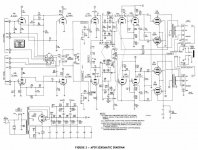
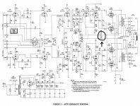
Anyways the schematic shows the NFB resistor as being 27k. The value in the unit was actually 19k. Now it would make sense to me that lower resistor values would allow for more negative feedback, correct? If this is true, i have had some very strange happenings. I started with a 33k resistor and moved all the way up to a 120k, and each time the amp grew in volume and seemed to really come alive. I figured the opposite would happen. Could anyone explain to me what's going on here? I'm lost as to why the circuit is behaving the way it is. The schematic is included for reference.
Another thing I wanted to fool around with was the negative feedback loop, experimenting with the resistor value.
I don't know much about it, but I've heard that it's used to stabilize, lower distortion, and increase gain of circuits. I've also heard that too much of it causes a very sterile "solid state" sound.
Anyways the schematic shows the NFB resistor as being 27k. The value in the unit was actually 19k. Now it would make sense to me that lower resistor values would allow for more negative feedback, correct? If this is true, i have had some very strange happenings. I started with a 33k resistor and moved all the way up to a 120k, and each time the amp grew in volume and seemed to really come alive. I figured the opposite would happen. Could anyone explain to me what's going on here? I'm lost as to why the circuit is behaving the way it is. The schematic is included for reference.
Attachments
Got your negative feedback ideas mixed up a bit. Adding more negative feedback reduces gain, reduces distortion, and if not done properly, causes instability. So when you increase the value of that feedback resistor, the feedback ratio decreases and the gain goes up - exactly what you are experiencing.
Binaural said:Anyways the schematic shows the NFB resistor as being 27k. The value in the unit was actually 19k. Now it would make sense to me that lower resistor values would allow for more negative feedback, correct?
In this schematic you have negative voltage feedback from the secondary of the output transformer (R27) and positive current feedback from the cathodyne phase inverter (R26). Both reduces the output impedance. Changing (or removing) voltage feedback may affect stability of the circuit.
Regards Andreas
Binaural said:quote:- < time the amp grew in volume and seemed to really come alive>.
Some years ago I did a fault find on a sim circuit; which had no fault on it. This type of circuit uses the resistance of 2 input tube heaters to set class A o/p stage cathode bias. Even the other channel is paralled. Replacing the two input tubes with other vendors types with slightly different heater current ratings can drastically effect emission. It's not my type of circuit arrangement.
As to nfb, I notice there is no phase correction cap on 1st amp stage anode (where nfb is connected to cathode). Reducing 27K to a lower value will increase suspectibility to HF instability, a square wave will easily show this up. By all means tweak it, if the amp makes a squealing noise when turned off or turned on with LS in circuit, instability is close.
richy
Richy,
What is this phase correct cap you speak of? Would it be a useful addition to the circuit? Also about the 12ax7's heaters in the bias circuit, the original bogen tubes are in those positions, so this should hopefully not affect the bias.
You also say that the OP stage is biased for class A? Also, what would happen if i completely removed the negative feedback? Any ideas?
I think it's a dangerous idea to remove the negative feedback look entirely. It's there for a reason.
Without negative feedback, the drivers will have way too much gain for the finals and will push them into distortion and probably into grid current at high signal levels. Could damage your amp.
Negative feedback loops in the kind of amp you have usually have a capacitor as well as a resistor in them to tailor the feedback at different frequencies to compensate for the fact that no device has a perfectly linear frequency response. The gain of the driving stages is carefully matched to the finals for a certain level of NFB to give the best output level, lowest distortion and best stability at the most common drive levels. Good amps have very carefully designed NFB loops and it's hard to improve on those of good manufacturers. If you want to tweak your NFB, do so in small increments paying attention to HF stability and distortion.
I have had some good results in subjective sound quality by replacing the cheap factory R/C with premium parts, notably replacing ceramic caps with silver mica ones.
There are good treatments of NFB loop designs in the popular books on tube amp design going all the way back the Audio Cyclopedia.
Good luck. And be cautious.
Binaural said:Richy,
What is this phase correct cap you speak of?
You also say that the OP stage is biased for class A? Also, what would happen if i completely removed the negative feedback? Any ideas?
You will need a oscilloscope and 1KHz square wave for optimising the phase comps cap on first stage. The value all depends on o/p tranny quality.
My guess is as no compensation caps are fitted in the amp, the front end triode HF roll off including the HF o/p tranny roll off (-3dB down point) is probably quite low, i.e 15KHz. In this case no small caps are fitted.
If you remove the global nfb, the loop gain will be at max. Ideal for guitar. In many amps typically 50mV for full o/p instead of 500mV (20dB nfb). Also the noise, microphony will be noticeable and in flighty amps, the amp might howl if LS is close by the 1st stage tube.
The annoying aspect without nfb loop is one hears everything in the house turning on/off, i.e fridges, light switches etc.
Failing experience and test equipment I would choose nfb resistor values +/- 25% from nominal. An amp should accept the variation. Ceramic caps have a tendancy to resonate, and any move to polyester or others is an advantage. The coupling caps to the output stage grids be a good quality type with decent voltage ratings.
Hope this helps
richy
It's worth keeping your eye on the value of the 12AX7 heater volts for the first two stages.
Great, thanks for the info. I had some time over the last couple of days to really sit down and dig into this. What I did was take a scope, with a calibrated 1K sine input and hooked up a 50K linear potentiometer in place of the NFB resistor. I set it so the amp will start clipping at 1.5V input. Does this sound about right? I then took the value the pot was at and fitted a resistor of close value. Is the capacitor really necessary in the NFB loop? If so how would I go about finding an optimum value. What should I look for on the scope? Also how can you tell by looking at the schematic that this amp is a class A amp? This is one thing I haven't learned yet. I know the basic differences between the classes, but not how to identify them on a schematic (if possible). Thanks, everyone has been more than helpful to me!
You can't tell one class from another from the schematic alone. You need to look at the operating points and load resistances.
The best hundred bucks you'll ever spend is buying Morgan Jones's two books. That will let you get a firmer handle on the theory rather than randomly flailing, and he even has a section on specifically how to tune feedback and compensation in a tube amp.
The best hundred bucks you'll ever spend is buying Morgan Jones's two books. That will let you get a firmer handle on the theory rather than randomly flailing, and he even has a section on specifically how to tune feedback and compensation in a tube amp.
I have also experimented with my amps feedback. I have a much more simple amp (6SL7 into a pair of 6L6GC). I put a 100k pot in for the 30k feedback resistor. It sounded less anemic as the resistance went up. I accidentally turned on the amp with pot set to low resistance and all sorts of hell broke loose...arcing across some tubes, nasty sound, etc...I shut it down quickly before any major damage....
I now have a switch to turn on 50k FB and turn off FB entirely. The original was 30k (this is a home brew jobbie a friend of a friend built)
I do have some major hum with less FB, but I have plans to add another RC filter to the power supply and maybe put DC on the heaters to reduce the hum.
I cannot detect "flabby bass" that no FB designs often have, so maybe I will leave it with no FB...
I should get MJ's books and tune the FB as Sy says. I just get monster headaches when I read too much.
SY said:John, Morgan's books are entertaining and astoundingly clear. Not a headache in the bunch.
Not quite so.There are some startling omissions.
SY.. My Morgan Jones book 3rd ed Vamps has no mention anything on pole/bode stability. (and I haven’t ripped the pages out..) I’m suprised at this omission and no mention with the feedback components. In fact I’m often referring to my switchmode bible. Which book(s) have you got ?
I differ with your intepretation on not being to detect class ABC from schematics. The PSU is often the give-away clue.
.John....One reason why your amp is class AB is that the current through the front end heaters is fairly constant from no to full load condition as the difference in class A even towards AB1(class B on peaks) is a mere 10% more. The long time-constant of the heaters evens this small difference out. If it was true class B or even class C then the ratio between no load and full load would be too large and this heater technique from o/p stage cathode currents cannot be used. The simple concertina phasesplitter cannot cope with class B demands, so again this can only work when no grid current flows, ie o/p stage in class A.
Advocates of the non Global feedback lobby often fail to realise it’s the absence of feedback that often causes more troubles!
A sine wave is for setting levels. One can easily determine the amount of global nfb by measuring voltage difference with nfb loop connected/disconnected. Log20 delta (Vout no nfb/Vout with nfb).
A square wave for a tube amp spells truth about its performance. No myth here.
richy
I spent months trying to design a indirectly heated pentode power amp with no negative feedback globally (all local). It was noisy, quirky, and did all kinds of strange things when you so much as put your hand near the tubes. It's a boat anchor-style guitar amp/multi-power amp public address, so the usual attempts to make it frequency flat were unnecessary...I just use a ~50-100pF cap in parallel with a 50k pot to find the sweet spot.
Now it's dead quiet, overdrives *better*. Too much NFB is just as oscillation prone as too little, and it all goes crazy when the amp is overdriven. I imagine though that applies to hifi as well, due to transients etc. I find it's better to use the global loop to nail down the hi frequency response and provide a bit of damping for the outputs, and then use local feedback elsewhere in the amp.
Done properly, NFB is important with pentodes, they're vastly different than triodes in that respect. Triodes have inherent NFB, pentodes need it developed externally for similar performance.
Since you have a scope you may want to check the frequency response of the amp with and without any nfb. You should see the low and high frequency response roll off earlier with no feedback.
As far as the cap goes.. I believe that it is used for phase correction. As different frequencies go from the input to the output of an amp there is a non equal shift in phase depending on the frequency. As you apply nfb from the output into the input of the amp and especially with a lot of nfb, there is a chance that one end of the frequency (I forget if it's high or low) will will wrap around and come back at positive feedback instead. So you end up having the amp starting to oscillate at certain frequencies with the other end of the scale is dampened. The cap is there to kinda straighten out the phase shift to keep it all negative feeback instead of mixed negative and positive feedback.
You can try different values of pico farad caps and see how they effect the overall frequency response of the amp.
-keith
- Status
- This old topic is closed. If you want to reopen this topic, contact a moderator using the "Report Post" button.
- Home
- Amplifiers
- Tubes / Valves
- Negative Feedback?