chromal said:The 'Class A P/P' really threw me for a loop. So, I can operate at class AB2 P/P with 1.8% THD at 26.5w Pout...
This is actually a Class AB1 (PP) spec. This is the one I selected for doing an 807 project. The Class AB2 spec is 80W out with THD= 3.0%. I just didn't need all that power. With the grid drivers I included, I'm getting a bit over 30W out since it can slip a bit into AB2 operation. The OPTs (Hammond, 30W rated) saturate before there's any clipping.
Class A P/P with 4.0% THD at 24w Pout, or Class A P/P triode-strapped for 0.6% THD at 6w Pout. All this according to this application data I found on the net... I'm surprised the class A P/P has more THD than the class AB2. I suppose it could be because of the selected positions along the tube curves...
It's always about what the loadlines say. Class A isn't necessarily a "magic bullet" that insures sonic goodness. It also depends on the type and what sort of harmonic distortion it produces. Lots of folks say that 6V6s sound especially good, since this type produces mainly h3, which isn't so dissonant as higher order harmonics.
Looks like I need to read and think some more about the long-tail pair, and how NFB would interact with the CCS requirements.
No big mystery about LTPs. Just set up your loadline, pick a Q-Point, and know that the LTP will give half the gain per phase. Your best bet with an LTP is active tail loading. This ensures AC balance, and also balances the harmonic distortion better than trying to force it with unbalanced plate resistors when you have a passive tail load.
Hmm, 7hz highpass to prevent DC-like OT loading? Sounds like something I read in M.Jones and since forgot.")
This is mainly to get very low frequencies out of the pass band. You get these infrasonics from such things as turn table "rumble" or the fact that vinyl disks aren't perfectly flat, or from the routine manipulation of guitar strings, etc.
Looks like I need to read and think some more about the long-tail pair, and how NFB would interact with the CCS requirements.
When a bipolar PSU is employed, the non-inverting grid is grounded and the inverting grid is driven. Adding loop NFB is very easy. "Lift" the non-inverting grid and apply the NFB to it. Since it's in the cathode circuitry, the CCS is not involved.
Hmm, 7hz highpass to prevent DC-like OT loading? Sounds like something I read in M.Jones and since forgot.
I'll go further. Set F3 between 15 and 17 Hz. O/P trafo core saturation, due to loop NFB error correction, is a MORTAL enemy. Don't let saturation happen! Remember, 31 Hz. is the lowest fundamental a double bass can produce.
hey-Hey!!!,
On loading...SE is fairly simple; the load line is simmply the primary's reflected load, as in 3k, 5k etc. PP in class A, each tube sees half the a-a load, so you'd draw a SE load line at a-a/2. Now in AB the power stage cuts off one tube at higher signal levels and the load goes to a-a/4 or a 2:1 variation as signal increases. This load variation leaves the power supply needing to supply extra current( over the idle value ) and raises the stakes/difficulty on regulation of B+. I'd advocate keeping to class A...
cheers,
Douglas

Thanks to everyone who has replied thus far-- so far, you guys have been a great sounding-board in working through some of the pre-planning for my first DIY amp.
Right now, I've been testing out various power supply layouts in the time-honored plywood prototype approach. Since my 320-0-320 0.105A / 6.3-0-6.3 3A tranny can't really handle the B+ current for two PP channels, I've been playing with a monoblock design for now until I can source two new smaller power trannies, or a larger tranny for a stereo amp.
I've been playing a bit with power supply designs using 'Duncan Amp Pages' PSUD2 software. Wow, fantastic for the price (free!). Its ability to simulate made non-intuitive aspects of power supply design visually make sense (like how putting a Cap in front of a choke after the rectifier section can drastically increase the final B+ voltage). I have a tenative design I've come up from using this software for my monoblock class-A (triode) PP 6BG6G amp, which this thread has been about thus far... BUT!
I also just ordered a Tubelabs Simple SE, which I may play with as the basis for a second 6BG6G/6BG6GA (6DQ6A? another 6v heater tophat pentode?) amp. I'll probably post my power supply / OT setup ideas for that later on.
Right now, I've been testing out various power supply layouts in the time-honored plywood prototype approach.
Since my 320-0-320 0.105A / 6.3-0-6.3 3A tranny can't really handle the B+ current for two PP channels, I've been playing with a monoblock design for now until I can source two new smaller power trannies, or a larger tranny for a stereo amp.I've been playing a bit with power supply designs using 'Duncan Amp Pages' PSUD2 software. Wow, fantastic for the price (free!). Its ability to simulate made non-intuitive aspects of power supply design visually make sense (like how putting a Cap in front of a choke after the rectifier section can drastically increase the final B+ voltage). I have a tenative design I've come up from using this software for my monoblock class-A (triode) PP 6BG6G amp, which this thread has been about thus far... BUT!
I also just ordered a Tubelabs Simple SE, which I may play with as the basis for a second 6BG6G/6BG6GA (6DQ6A? another 6v heater tophat pentode?) amp. I'll probably post my power supply / OT setup ideas for that later on.
hey to all from bombay,
this is an interesting thread. i came across it while trying to figure out what to do with the 6BG6G pair I have lying around.
i thought it would be neat to be able to put them into an electric bass amplifier pushing about 50W - is this possible, with about 500V on the plates?
i can get quite decent toroids custom wound here according to my specs, so meeting the circuit requirements is not a problem. is this possible though? perhaps running 2 at a more conservative voltage?
thanks for any and all advice!
flood said:i thought it would be neat to be able to put them into an electric bass amplifier pushing about 50W - is this possible, with about 500V on the plates?
so I've heard different things. others please chime in: the original 6BG6G is a lot like an 807 tetrode, and maybe has less power handling capability than the 6BG6GA? Anyway, my Tung Sol 6BG6G sheet says the tube has a maximum plate dissipation of 20w, but I have some application notes that claim if you run it in Class AB2 PP you'll get a Pout of 26.5w, I believe -per tube-? Anyway, that's with an anode voltage of 360v, Vg2 @ 270v, grid biased to -22.5v. Anode current at 69mA, Zout 6600. THD==1.8%
chromal said:so I've heard different things. others please chime in: the original 6BG6G is a lot like an 807 tetrode, and maybe has less power handling capability than the 6BG6GA? Anyway, my Tung Sol 6BG6G sheet says the tube has a maximum plate dissipation of 20w, but I have some application notes that claim if you run it in Class AB2 PP you'll get a Pout of 26.5w, I believe -per tube-? Anyway, that's with an anode voltage of 360v, Vg2 @ 270v, grid biased to -22.5v. Anode current at 69mA, Zout 6600. THD==1.8%
The 6BG6 is the octal version of the 807. (807 Application Report) The operating point mentioned here is for Class AB1 operation. Push 'em into Class AB2, and you get 80W at ~3.0% THD. You can get as much as 120W, but that's almost Class B, and is likely to sound horrible. Of course, that was for an AM plate modulator for a ham rig where you don't need good fidelity anyway.
hey,
that's some useful information right there. i'm not too worried about THD, since i plan to use it for bass and actually want a bit of "character" to the sound... unless it's going to sound downright horrible, flabby and/or gated, i wouldn't mind giving it a shot
i'm just doing this amp for kicks. i think a class D design with an SMPS would be a little more forgiving on my back
I've been using 6BG6GA's in a Simple SE for a while now. You won't be disappointed. I've tried a pair of old 6BG6G's and they sounded great, but couldn't take the ~27w dissipation (guessing from tubelabs chart). The GA's may be able to take a good beating depending on the manufacture.
One thing about these 6BG6 tubes is they can take a good high voltage. Anyone have thoughts about using the 640vct power transformer with a bridge rectifier? Electrolytics probably aren't an option any more in a power supply, but they can be gotten reasonably
One thing about these 6BG6 tubes is they can take a good high voltage. Anyone have thoughts about using the 640vct power transformer with a bridge rectifier? Electrolytics probably aren't an option any more in a power supply, but they can be gotten reasonably
6L6G/6L6GB/6BG6G/6BG6GA SE OTs
So one of the questions on my mind is the ideal primary impedance for a 6BG6G SE OT. I've read different things, primarily,
6L6GB: A SE Zout = 4600
807: A SE Zout = 6000 for 'autobias resistor,' 5000 for -20v grid bias. autobias? Is that like cathode bias?
I've primarily been looking at Edcor OTs at the suggests of others here and because of their price/performance:
CXSE25-4-5K
CXSE25-4-6.5K
But am not sure which would be the best choice for tube/loudspeaker rolling (I have two pairs of 4ohm and three pairs of 8ohm loudspeakers, would ideally be able to explore both). Should I ask about two secondary output impedences, perhaps, or hook up 8ohm speakers to the 4ohm outputs and hope it's 'close enough' ?
Well, nevermind. I just ordered some Edcor XSE SE OTs. Ouch, 2-3wk turnaround. WEll, I'm glad they seem busy with orders in this economy. If they're not the best choice, ohwell, at least they were cheap at $20 per. (XSE15-4-5K) Although some 'net reviewers suggest they exceed their official specified bandwidth, I sort of balk at the official lofi-ish spec of 70-18kHz. Anyway, I can always drop in CXSE25-4-5K OTs later, if I want.
I also picked up an unlisted Edcor Power Transformer they had with 370-0-370@200mA, 6.3@4A, 5@2A) which I think will make a decent power supply tranny for my Simple SE / 6BG6G project. Still haven't figured out how I would power a stereo version of my 6BG6G class-A PP amp project, nor whether I want an integrated stereo amp or two monoblocks.... I'll continue to muddle forward with my 1-channel class-A PP prototype using my existing power and output trannys.
I also picked up an unlisted Edcor Power Transformer they had with 370-0-370@200mA, 6.3@4A, 5@2A) which I think will make a decent power supply tranny for my Simple SE / 6BG6G project.
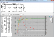
Still haven't figured out how I would power a stereo version of my 6BG6G class-A PP amp project, nor whether I want an integrated stereo amp or two monoblocks.... I'll continue to muddle forward with my 1-channel class-A PP prototype using my existing power and output trannys.Here, I've attached a .PNG image of the schematic and a simulation of a possible B+ supply for the 6BG6* class-A(triode) PP 1ch amp. a 4k resistive load is intended to represent two ~42mA (triode-strapped) anode loads on the PP transformer.
the white line is the voltage presented to the OT's primary center tap.
T1 is my 320-0-320@105mA power tranny (320@117 input. my input's more like 120-121, so 333-0-333 in the simulation)
L1 is a hammond 169S 4H 225ma 500v choke.
C1, C2, C3 are 500v caps. (note that C1 and C2 are shown as 'ringing' into the near 550v territory, but what design alterations I could make aren't clear to me...
R2 is intended to represent the OT/tube load at quiescent.
My goal here is to provide a ripple filter and current source for a 325v plate voltage, 42mA Ia per tube, as per the application data for a triode-strapped 6BG6G class-A P/P from tung-sol, which rates each tube at a Zout of 8000 under this configuration.
Is C3 enough of a reservoir at 47uF? I have a bag full of these 47uF@500wvdc electrolytics....
Attachments
- Status
- This old topic is closed. If you want to reopen this topic, contact a moderator using the "Report Post" button.
- Home
- Amplifiers
- Tubes / Valves
- experimental 6L6G / 6BG6G amp design brainstorm