I have been building a triode-connected push-pull KT88 amp for over a year now that has a mosfet source follower driver, my first tube amp. Until now, I have been a bit chicken to remove the grid stoppers because I feared that the thing would just oscillate or something. Over the past couple of weeks, I cleaned up the wiring and pulled out the grid stoppers.
I fired it up and watched for oscillations. Nothing. I started to play some music, which sounded noticeably better than before at loud volume levels, especially the high frequencies. The lows are a bit lacking, but I'm still running open-loop.
I watched with a scope on the speaker terminals. I was getting music peaks up to about 30V, which would imply over 50W if I assume a constant impedance of 8 Ohms for my speakers. I switched over to a 1KHz sine wave input and figured that I would just flick the volume up really quick to see where the limit was. (I don't know how fragile the grids of the EH KT88s are, don't want to melt them.) I got the output up to about 30V peak before it seems to start leveling off the peaks. They were nice and rounded, not a sharp limit. All of this was into my cheap 8 Ohm test speakers. I decided to flick the volume control up one more time to see it again. Well, you know what happened next, right?
Strange sounds, then kind of a constant buzzing followed by a mushroom cloud of smoke above a capacitor bank. I hit the power switch fast. After the smoke cleared, I started to assess the damage. The cap that blew was associated with the +300V supply, which is only serving as the positive rail for the source followers at this time. A while back, I got sick of changing series dropping resistors every time I made adjustments to current draw in stages, so I put in simple source follower regulators as an alternative. No more changing out series dropping resistors. The cap that blew was the output bypass cap for that regulator. It was being charged by the mosfet and being discharged through the source follower drivers into the grids of the KT88s. I'm guessing that I exceeded the ripple current rating of the 22uf Xicon cap. I'm at 85% of the voltage rating, maybe some more margin is in order there. Anyway, I don't think I'll push things that hard any more. I'm afraid for my poor grids.
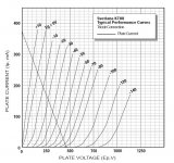
Now let's look at the load line. I'm running these at 50mA quiescent, but just drew the class B load line because I'm lazy. 30V peak implies about 21Vrms. 21Vrms into 8 Ohms implies 56Watts. 56Watts into 8 Ohms through a 5K output transformer implies a 300mA peak change in current. Since I am biased at 50mA, this implies that peaks are reaching 350mA. Wow, that's only 25V at the plate according to these curves. When I get a decent probe, I'll verify that by direct measurement. I imagine that grid current is pretty heavy up here. Actually, I know it is.
Again, the sweeping assumption I am making here is that my speakers are actually 8Ohms at 1KHz. This may not be true. It would be nice to repeat the experiment into a resistive dummy load, but I've got some work to do first.
I fired it up and watched for oscillations. Nothing. I started to play some music, which sounded noticeably better than before at loud volume levels, especially the high frequencies. The lows are a bit lacking, but I'm still running open-loop.
I watched with a scope on the speaker terminals. I was getting music peaks up to about 30V, which would imply over 50W if I assume a constant impedance of 8 Ohms for my speakers. I switched over to a 1KHz sine wave input and figured that I would just flick the volume up really quick to see where the limit was. (I don't know how fragile the grids of the EH KT88s are, don't want to melt them.) I got the output up to about 30V peak before it seems to start leveling off the peaks. They were nice and rounded, not a sharp limit. All of this was into my cheap 8 Ohm test speakers. I decided to flick the volume control up one more time to see it again. Well, you know what happened next, right?
Strange sounds, then kind of a constant buzzing followed by a mushroom cloud of smoke above a capacitor bank. I hit the power switch fast. After the smoke cleared, I started to assess the damage. The cap that blew was associated with the +300V supply, which is only serving as the positive rail for the source followers at this time. A while back, I got sick of changing series dropping resistors every time I made adjustments to current draw in stages, so I put in simple source follower regulators as an alternative. No more changing out series dropping resistors. The cap that blew was the output bypass cap for that regulator. It was being charged by the mosfet and being discharged through the source follower drivers into the grids of the KT88s. I'm guessing that I exceeded the ripple current rating of the 22uf Xicon cap. I'm at 85% of the voltage rating, maybe some more margin is in order there. Anyway, I don't think I'll push things that hard any more. I'm afraid for my poor grids.
Now let's look at the load line. I'm running these at 50mA quiescent, but just drew the class B load line because I'm lazy. 30V peak implies about 21Vrms. 21Vrms into 8 Ohms implies 56Watts. 56Watts into 8 Ohms through a 5K output transformer implies a 300mA peak change in current. Since I am biased at 50mA, this implies that peaks are reaching 350mA. Wow, that's only 25V at the plate according to these curves. When I get a decent probe, I'll verify that by direct measurement. I imagine that grid current is pretty heavy up here. Actually, I know it is.
Again, the sweeping assumption I am making here is that my speakers are actually 8Ohms at 1KHz. This may not be true. It would be nice to repeat the experiment into a resistive dummy load, but I've got some work to do first.
Attachments
More knowledge to share, even though it doesn't seem that its terribly interesting to everyone. I've always enjoyed taking the less traveled road.
I had a chance to go through the power supply and it seems that in addition to blowing up the power supply cap I blew the mosfet. (Again, I'm using a simple source follower regulator mainly so that I don't have to change out dropping resistors every time I change current in various stages.)
This mosfet passes about 20mA and drops about 200V, so it dissipates 4W. It is bolted to the chassis, which is .125" aluminum. Of course, as the grids start consuming a lot of current, my theory is that this mosfet overheated and blew. It failed as a short taking the 350V cap at the output up to 500V, blowing it. I wish I had had the ability to measure current into the grid during this test, it would have been interesting to see how much peak current was being drawn.
As I cranked up the volume, output looked like a nice sine wave until output reached 60Vpk-pk. Clipping was pretty soft with a nice round mound at the top of the clipped sine wave.
Now the bad news: I think I toasted my new EH KT88s. After fixing the power supply I tried bringing everything up and one of the tubes had about 40mA at idle with -85V on the grid (typically I need about -55V for 50mA) Worse, the current was slowly climbing. When I powered down the amp, one of the other tubes arced and killed its source follower driver.
After reading some on the subject, it seems that control grid over-dissipation results in the gold plating boiling off which contaminates the tube vacuum and the cathode surface. This is consistent with apparent early runaway conditions in my tube.
I think that since the source followers have the capability to destroy the tubes, I would like to put in some grid current limiting resistors at their outputs. I know that this will add to distortion, but I don't want to be rockin' out and destroy my tubes again. I think that I will start out with about 200Ohms and work my way down.
My plan will be to buy a HV differential probe (I've been wanting one for a long time anyway) and target a grid current limiting resistor that will not allow more than .5W dissipation in the grid and see how that performs/measures, since common 6l6 operating points use almost this much. TT21(transmitting version of KT88) data sheets list max control grid dissipation as 2W.
If anyone has any advice on this stuff, I would love to hear it.
SpreadSpectrum said:
As I cranked up the volume, output looked like a nice sine wave until output reached 60Vpk-pk. Clipping was pretty soft with a nice round mound at the top of the clipped sine wave.
Now the bad news:
The big avoid is testing with a continuous sinewave and getting carried away is brutal for the machinery in AB2. Tempting it maybe, but realistically in music the peaks are short lived duration.. Continuous run, the peak anode current will test power supply, the whole lot. Grid dissipation has a long time constant and hard signals will heat up and eventually sag.
I ran an ECL82 7W amp in AB2, after abandoning some conventions got 20W peak but one must be fair on tubes.
richj
I'm thinking I should build a test waveform with only occasional large peaks for this kind of testing. Easy enough to do with software then burn it to a CD.
I just got carried away in the excitement and wanted to know how far it would go. Now I know. I won't be doing it like that again.
I just got carried away in the excitement and wanted to know how far it would go. Now I know. I won't be doing it like that again.
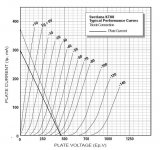
Okay, I measured the impedance of the speaker at 1k and it came out to 10 Ohms. I was delivering approximately 45W into the speakers. This also means my tubes were seeing a plate to plate load of 6250 Ohms during my test.
If my math is correct, 45W with a plate to plate load of 6250 puts peak current at 290mA. This puts the plate at something like 10V without taking transformer losses into account. I don't believe that it was quite that low, but you can see why grid current would be extraordinarily high here as grid voltage and plate voltage were about the same. Fun stuff, I didn't think I'd be able to get the plates that low. I need to get some good probes so that I can verify these calculations with actual measurements from the plates.
Attached is a new load line added to show operation into a 10Ohm secondary load. Feel free to point out any errors in my math.
If my math is correct, 45W with a plate to plate load of 6250 puts peak current at 290mA. This puts the plate at something like 10V without taking transformer losses into account. I don't believe that it was quite that low, but you can see why grid current would be extraordinarily high here
as grid voltage and plate voltage were about the same. Fun stuff, I didn't think I'd be able to get the plates that low. I need to get some good probes so that I can verify these calculations with actual measurements from the plates.Attached is a new load line added to show operation into a 10Ohm secondary load. Feel free to point out any errors in my math.
Attachments
Wavebourn said:Do you have a gate stopper of your source follower? The cap could be easily blown up by MOSFET's oscillations.
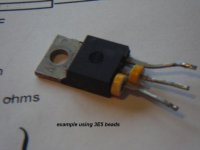
Quite right and often 100% ignored even by experienced equipment designers. A cheap ferrite bead (make sure is insulated type) on the mosfet gates and some cases also do drain as well) can cure RF evils and mystery RFI that one cannot see on oscilloscope. A resistor and/or ferrite physically on the leads of the device. pic encl
By the way; when working with RF devices I always have a small AM/FM radio close by; this will immediately put up oscillations and save a helluv'a lot of trouble.
richy
Attachments
SpreadSpectrum said:Now the bad news: I think I toasted my new EH KT88s. After fixing the power supply I tried bringing everything up and one of the tubes had about 40mA at idle with -85V on the grid (typically I need about -55V for 50mA) Worse, the current was slowly climbing. When I powered down the amp, one of the other tubes arced and killed its source follower driver.
"Too much power is almost enough! Turn it up till it explodes - then back up just a little."
George would approve.

Pseudotriodes don't work well in Class *2. If you look at the Class AB2 data for the 807, it mentions input power levels of about 100mW total. That means very little grid current, and it was never designed to hold up to the grid currents that will flow in triode mode. Take a good look at any triode that was intended for such useage, and you are likely to see that the control grid posts have radiator wings attached and/or that the whole structure is a good deal more robust than what you'll find in most pentodes.
One project with 807s will slip a bit into Class AB2 since it includes grid drivers, but will max out when the OPT core saturates a bit above the 30W level. Another project never gets there since it can put out some 37W, and the OPT is rated for 30W, and doesn't go much higher anyway.
Example; one of the tubes (yes it's an RF transmit tube) that lists grid 1 current is the GE 6146 and it isn't much.
http://www.frank.pocnet.net/
r:-
http://www.frank.pocnet.net/
r:-
Good to know!richwalters said:Quite right and often 100% ignored even by experienced equipment designers. A cheap ferrite bead (make sure is insulated type) on the mosfet gates and some cases also do drain as well) can cure RF evils and mystery RFI that one cannot see on oscilloscope. A resistor and/or ferrite physically on the leads of the device.
By the way; when working with RF devices I always have a small AM/FM radio close by; this will immediately put up oscillations and save a helluv'a lot of trouble.

Do you have a gate stopper of your source follower?
I have a 1k carbon comp soldered directly to the gate pin.
I don't think there was any oscillation in the amp, but I could be wrong. I will have the radio turned on next time I play with it, but it will be a while. Gotta get some new tubes and upgrade the test equipment. I'm thinking of getting the Sovtek 6550s with the plastic bases. That way I won't have to cry as much when I burn 'em up.
Pseudotriodes don't work well in Class *2.
How come nobody ever told me that before? How about 300Bs? I don't think I could experiment on tubes that expensive.
Well, I am still determined to get as much power out of these pseudotriodes as possible without hurting them. I plan on putting grid current limiting resistors on the outputs of the source followers. I plan on starting out with about 200 Ohms and working my way down. I've got to buy a couple of probes and a new set of tubes first so it will be a little while before I get this sorted out.
I have pounded on the grids of some cheap Chinese KT88's without damage. I know that the grid current is considerably more than you imagine. I have seen 100+mA peaks on sweep tubes.
I was googling up some information on RF linear amplifiers for ham radio and I found several references and a few explicit warnings about the fragility of gold plated grids under grid current. Apparently the gold will migrate causing permanent damage.
I got some "pre auditioned" (used) EH tubes cheap from a tube seller and I didn't even know that they had a gold grid. I guess it is fortunate that I have not tried my EH KT88's in such an application. They have lived happily in a Simple SE for their entire lives.
I tend to use cheap or expendable tubes for these type of experiments. This is why I bought up a bunch of $1 and $3 sweep tubes last year. I can (and will) turn them up till they explode.
Pushing the Chinese KT88 into A2 in SE didn't buy much extra power, but nothing bad happened. I have not yet tried them in a P-P amp, but those experiments are coming. At first they will be done on $1 tubes. I also have some really useless KT88's that I will "test", but the test may be meaningless since these tubes are prone to blowing up without provocation.
It is unfortunate that someone else had to learn, but my EH KT88's won't go there, even for $10 each.
I was googling up some information on RF linear amplifiers for ham radio and I found several references and a few explicit warnings about the fragility of gold plated grids under grid current. Apparently the gold will migrate causing permanent damage.
I got some "pre auditioned" (used) EH tubes cheap from a tube seller and I didn't even know that they had a gold grid. I guess it is fortunate that I have not tried my EH KT88's in such an application. They have lived happily in a Simple SE for their entire lives.
"Too much power is almost enough! Turn it up till it explodes - then back up just a little."
George would approve.
I tend to use cheap or expendable tubes for these type of experiments. This is why I bought up a bunch of $1 and $3 sweep tubes last year. I can (and will) turn them up till they explode.
Pseudotriodes don't work well in Class *2.
Pushing the Chinese KT88 into A2 in SE didn't buy much extra power, but nothing bad happened. I have not yet tried them in a P-P amp, but those experiments are coming. At first they will be done on $1 tubes. I also have some really useless KT88's that I will "test", but the test may be meaningless since these tubes are prone to blowing up without provocation.
It is unfortunate that someone else had to learn, but my EH KT88's won't go there, even for $10 each.
Pushing the Chinese KT88 into A2 in SE didn't buy much extra power
I got more than twice the power in this push-pull amp.
It was working well and sounding great until I did the high-powered sine test. Only when I turned it up to the point where there was serious visible distortion did I fry the tubes. (They died in about a second, in case anyone is curious.)
I'm going to buy both a standard high voltage probe and a high voltage differential probe so that I can measure grid current and voltage at the same time. Then tweaking the value of the grid current limiter will be much easier. I am hoping that I can choose a resistor value that will not have too much impact at lower levels of grid current but will limit some of the extreme current peaks so that overall grid dissipation stays pretty low. My theory is that extreme grid current flow occurs pretty close to clipping anyway so starting the clipping process a bit earlier will have minimal impact on the sound of the amp.
I've got some 6BG6G's and 6L6GC's lying around, and a few OPT's
Did someone say 6L6GC in AB2? Look at this thread. Tons of power, no fireworks. The schematic of the driver used in those experiments is in post #132. I have a new PC board laid out that uses a direct coupled pair of 6SN7's, but I haven't had the time to make one yet. Maybe next weekend.
http://www.diyaudio.com/forums/showthread.php?s=&threadid=133034&highlight=
Well, for the follower stage I used supplies of +200 and -300. Load resistor was a Caddock 50K thick film resistor. I'm not a resistor snob or anything, I just liked how I could bolt that resistor to the chassis right next to the tube socket and bend the lead into a hook to solder to the pin. I did the same with the mosfet(FQPF2N90). Leads are extremely short this way.
The output tubes bias up with about -50V on the grids so current through the follower is 5mA. I was going to test the effect of changing the mosfet's bias current as far as distortion goes.
As far as the test amp goes, it is a 6SN7 grounded cathode gain stage with an unbypassed cathode and 50k load resistor at +500V followed by a LTP with CCS (BJT cascode) again with 6SN7 and 50k load resistors at +500V which feeds the mosfet followers.
Sorry I don't have a nice pretty schematic for this amp. I have a schematic for how I want to make it but not how it currently exists. Feel free to ask any more questions if this is not clear.
- Status
- This old topic is closed. If you want to reopen this topic, contact a moderator using the "Report Post" button.
- Home
- Amplifiers
- Tubes / Valves
- KT88 AB2 Experiences