BC558 beta varies from 110 minimum to 800 max @ 2mA 5VCE.
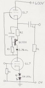
I don't see how this oversimplified current load (in the middle
of a totem, is "load" more descriptive than "source" or "sink"?)
can be precisely computed in advance. Gonna need tweaking.
The total voltage drop of the active current load should be the
same as the two IR LEDs after all is said and done. Correct???
I'm thinking R1 should be approximately R2*Beta? That should
bias the base to emitter junction right about dead center of the
totem. But we don't know R2 just yet.
For R2 then: Whatever voltage the two IR LEDs drop. Subtract
the base to emitter drop of Q1. Divide the leftover load voltage
in half. Half to drop across the collector, half to drop across R2.
Ohms law figures R2 from there.
Don't know if this is "optimal", but it ought to be in the ballpark.
As I said, you are gonna need to tweak depending on Beta(HFE).
R1 with the cap probably ought to be the pot... Might make less
noise than R2 as the adjustible.
Adding a resistor across C1 makes biasing much less dependant
upon the exact known value of an unknown Beta. And you may
then be able to dispense with a trimpot.
The more severe PSRR prob is with the Triode cathode follower
up top. The lower Triode is exposed to almost constant current,
but the upper is fully vulnerable to B+ noise.
I think I'd ditch the whole upper half and replace with NPN or
N-Channel. Configured either as Mu Follower or Anti-Triode.
Once you free your mind to throw sand at solving the top half,
whats the big diff? Except that the overall PSRR is much better.
And you don't have to float a heater.
If I was gonna bypass C1 with a resistor and lower R1 to keep
the base cenetred in the totem, it might just mitigate the issue
of an unknown beta.
But also makes for a big leak that circumvents the active part
of this load. The problem that dynamic impedance here can be
no higher than R1. Because you always got AC short across C1.
Maybe lowering R1 to lessen dependence on Beta isn't helping.
Hmmm, how to fix? I don't care for this active load, just scrap it.
The current and voltage here are small. Have you considered
the flat plateau of a JFET? Either in self bias, or with a trimpot.
Perhaps Toshiba 2SK373?
- Status
- This old topic is closed. If you want to reopen this topic, contact a moderator using the "Report Post" button.
- Home
- Amplifiers
- Tubes / Valves
- Beta followers, biasing.