Many of you know that 2008 has been a difficult year for me. Layoffs at work, two very ill close relarives, yada yada, yada.....
I was thinking over the Christmas holidays that I had gone through all of 2008 WITHOUT BUILDING A SINGLE AMPLIFIER.
I started a 307A SE amp, but never finished it. I also came to the realization that EVERY amp that I have built since 2000 has been a SE HiFi amp. No guitar amps, no P-P amps, NADA. Talk about being in a rut. What am I going to do about it? Build an amp, a P-P amp, a complete amplifier, chassis, cabinet, stand alone, no external power supply, a real useful amp.
Well, my budget right now is nearly zero, so I got to use what I got, but I got a lot. Last year did not result in any completed amplifiers, but it did host a few experiments, P-P experiments too! The tube sale at AES resulted in some glowing tubes, and some seriously impressive power output numbers from some sweep tubes using conventional grid drive, screen drive, and cathode follower operation. It also resulted in a big box of cheap tubes to experiment on. I recently scored 8 X 6LR6 sweep tubes on Ebay for under $30. I feel the need to make em glow. I got a new power supply that produces 600 volts at 1.5 AMPS! No more power supply limitations. I have a small collection of P-P OPTs in sizes from 10 to 400 watts. Whats missing? A suitable driver for all of this of course.
I have been working on this driver circuit on and off over the past two years. There have been several changes, and new directions during that time. I have now realized that It may be possible to come up with a "universal" driver circuit that could satisfy most, if not all of those requirements. This driver circuit is not done yet, but I better start chronicling it now before I forget some of the important details. Time is limited now, so it may take a few days to catch up to where I am at now. The driver will be used to torture a few tubes, learn a lot of new things, and most importantly, build at least one amp. Hopefully more than one. I will test build (external supplies, no chassis) several kinds of amps based on some of my recent "experiments". I plan to post them all here.
"Tubelab" is known for SE HiFi amps, but long before I had a web site, I built other amps. Yes, solid state amps, tube, and hybrid, guitar amps, and HiFi amps. All of them were P-P except for some "Champ" clones. I built a few HiFi amps, mostly P-P leading up to the 300Beast, and then I got the SE fever.
Well, this P-P driver actually started about 10 years ago with my last P-P amp, the 300Beast. I threw this amp together in a hurry and used some rather cheap components but the sound it produces is amazing. It is the only amp that I have saved all of this time, but sadly, it has died. One of the reasons for this board design is to build a new Beast, so the board must be capable of driving push pull 300B tubes, and it must sound as good as the original Beast.
The Driver board used in the original 300Beast used a 5751 in LTP for the first stage. It used a pair of 6FQ7's wired in SRPP that are also cathode coupled as the "LTP" second stage. Kind of wierd, but it worked good. I never drew up a complete schematic though.
It's late, more tomorrow.
Attachments
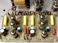
OK, here is a schematic that I found on a hard drive that came from the time frame that the amp was built. This is NOT from the actual design (since it is a single channel), but was likely from a test board that I did during the amp development. I am not 100% sure that it matches the schematic of the 300Beast amp.
I designed this amp about 10 years ago. I didn't know about CCS chips then, so LTP's use "tails" made of resistors off of -300 volts.
The 300Beast is still repairable (the photoflash grade elecrtolytics in the supply are shorted) so I do not want to disturb it until I have built something that sounds as good. It is still my reference P-P amp.
Attachments
The 300Beast amp has served me well over the past 9 years. It has however been a bit unusual. When I made it, it was an experiment. It was my first foray into "expensive" audiophile tubes. The amp was built using cheap components including some "guitar amp" OPT's and "ceiling fan" coupling caps. It does sound very good, and I have yet to build another amp with the punch and dynamics that the 300Beast delivers. Early on I made several attempts to upgrade the Beast (UTC OPT's, WonderCaps, etc....). Every time I wound up putting it back the way it was when I built it. It has remained untouched for the past 6 years. I decided that I would not touch it until I built something better. So, it is finally time to build something better.
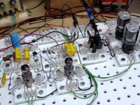
A couple of years ago, SY mentioned some extreme power that he was getting from a single pair of sweep tubes using screen drive. I had read about some commercial screen driven amps (Berning) but never tried it. I had just developed this breadboarding system, so I screwed together a screen drive amp using a pair of $3 sweep tubes, and yes some serious power flowed forth. Screen drive requires some serious drive voltage, hundreds of volts P-P and the driver must source screen current which could be tens of milliamps. The current is not an issue with PowerDrive, but the voltage requirements are not trivial.
I threw together this complete amp breadboard in one Saturday afternoon. I proceeded to torture it for a day or two, and then took it apart in order to build something else. This guy had no problem making 80 watts, and did so without a hint of distress. I knew that I wanted to revisit screen drive some day, so I actually drew a schematic of my creation this time.
Attachments
More info about this amp can be found at the bottom of this page:
http://www.tubelab.com/6AV5.htm
The schematic is included here.
OK, the new driver board needs to be able to deliver the voltage and current necessary for screen drive.
http://www.tubelab.com/6AV5.htm
The schematic is included here.
OK, the new driver board needs to be able to deliver the voltage and current necessary for screen drive.
Attachments
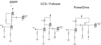
A question I got via email back when I posted the screen drive schematic was "What happened to the SRPP, don't you like them anymore"? Well The SRPP was in vogue when I did the 300Beast, and it seemed to work well in that design. I have learned a lot in the last ten years, especially in the judicious application of silicon in tube amplifiers, so I no longer believe the SRPP is of use here. Why? PowerDrive.
First we need to analyze what an SRPP is. See the first diagram on the left. The bottom triode is just a typical common cathode amplifier stage. The top tube is a cathode follower that also functions like a CCS. How? The top tube's grid is connected to the plate of the bottom tube through a grid stopper resistor, which can be ignored for analytical purposes. The plate of the top tube is connected to B+, sounds like a cathode follower to me. It would be if the cathode had a resistor to ground.
The cathode of the follower has a buffered and almost identical copy of the signal on the bottom tube's plate. The "magic" happens when we connect that resistor to the bottom tube's plate instead of ground. Now we have a resistor with an almost identical AC voltage on each end. This would mean that the current through the resistor does not change with signal, which is the definition of a CCS. Now the cathode follower is not perfect, so the CCS isn't either. The "Kimmel" or Mu follower improves on the SRPP by using a pentode for the top tube because a pentode makes a better follower than a triode does.
We can seperate the follower from the CCS as shown in the middle diagram. In theory the CCS can be made better by removing the follower duty. It could be implemented with a tube or silicon components. A silicon based CCS will have a lower minimum operating voltage, which is important when we need a bunch of output voltage swing. The follower likewise could be implemented with a tube or a mosfet. A mosfet has a much higher Gm than any tube, and will make a far better follower than a tube if a few guidelines are followed.
When I was exploring the limits of "cranked to 11" guitar amps I learned about blocking distortion. I learned that a heavy enough overload could actually silence the amplifier for a fraction of a second under the wrong conditions. Guitar players called this effect "farting out", and it is generally an unwanted phenomenon, unless you are Neil Young. The short story is that the capacitor and bias resistor on the output tubes grid are to blame, and must be eliminated. See the PowerDrive page for the long story.
http://www.tubelab.com/powerdrive.htm
OK, the circuit on the right can be made out of the middle circuit just by rearanging a few components. This is what I call PowerDrive. In my testing it delivers more output voltage, nearly unlimited output current, and far lower distortion than a SRPP or Mu follower, so long SRPP.
Attachments
There is another option that is half way between SRPP and Mu follower. Take a look at the IXGH6N170 above the 3C24 in this link:
http://www.diyaudio.com/forums/showthread.php?postid=1707173#post1707173
This has been referred to as accurate complementary drive or "anti-triode" in previous discussions. The idea being that the top device produces current variation which if summed with the bottom device's variation, would be a constant. (the bottom 120R resistor actually needs to be a little bigger than the top 120R when using finite gain devices on top, to allow for some AC gate drive signal generation) The accurate complementarity is intended to preserve the bottom single ended gain tube's characteristic sound.
The anti-triode....scheme should work well for a non-grid current tube drive since both devices operate with near constant current then.
Also, take a look at this scheme for avoiding blocking distortion:
http://www.diyaudio.com/forums/showthread.php?postid=1689375#post1689375
Normally Rk1 would = Rk2 to symmetrically neutralize the blocking effect at large signal, but some interesting results may be possible by making Rk2 smaller, so that grid bias will be decreased at some signal level up until g1 conduction restores neutrality by symmetry. This could be used to decrease the grid bias for "efficient class A" operation with increasing signal amplitude. (so it operates with a low idle current without sound signal present, and then increases the idle current to remain in class A with an increasing signal)
Finally, take a look at the 6GF5 for a HV driver tube. 770 V B+ rating, 9 Watts diss (in HO mode). This tube is just a 6GE5 with a smaller plate and stuck in a smaller bottle. The screen voltage won't take that much B+ though in triode, so some kind of "Schaded" feedback to g1 or g2 would be needed for lowering output Z.
Don
tubelab.com said:A question I got via email back when I posted the screen drive schematic was "What happened to the SRPP, don't you like them anymore"? Well The SRPP was in vogue when I did the 300Beast, and it seemed to work well in that design. I have learned a lot in the last ten years, especially in the judicious application of silicon in tube amplifiers, so I no longer believe the SRPP is of use here. Why? PowerDrive.
First we need to analyze what an SRPP is. See the first diagram on the left. The bottom triode is just a typical common cathode amplifier stage. The top tube is a cathode follower that also functions like a CCS. How? The top tube's grid is connected to the plate of the bottom tube through a grid stopper resistor, which can be ignored for analytical purposes. The plate of the top tube is connected to B+, sounds like a cathode follower to me. It would be if the cathode had a resistor to ground.
The cathode of the follower has a buffered and almost identical copy of the signal on the bottom tube's plate. The "magic" happens when we connect that resistor to the bottom tube's plate instead of ground. Now we have a resistor with an almost identical AC voltage on each end. This would mean that the current through the resistor does not change with signal, which is the definition of a CCS. Now the cathode follower is not perfect, so the CCS isn't either. The "Kimmel" or Mu follower improves on the SRPP by using a pentode for the top tube because a pentode makes a better follower than a triode does.
We can seperate the follower from the CCS as shown in the middle diagram. In theory the CCS can be made better by removing the follower duty. It could be implemented with a tube or silicon components. A silicon based CCS will have a lower minimum operating voltage, which is important when we need a bunch of output voltage swing. The follower likewise could be implemented with a tube or a mosfet. A mosfet has a much higher Gm than any tube, and will make a far better follower than a tube if a few guidelines are followed.
When I was exploring the limits of "cranked to 11" guitar amps I learned about blocking distortion. I learned that a heavy enough overload could actually silence the amplifier for a fraction of a second under the wrong conditions. Guitar players called this effect "farting out", and it is generally an unwanted phenomenon, unless you are Neil Young. The short story is that the capacitor and bias resistor on the output tubes grid are to blame, and must be eliminated. See the PowerDrive page for the long story.
http://www.tubelab.com/powerdrive.htm
OK, the circuit on the right can be made out of the middle circuit just by rearanging a few components. This is what I call PowerDrive. In my testing it delivers more output voltage, nearly unlimited output current, and far lower distortion than a SRPP or Mu follower, so long SRPP.
Hi George,
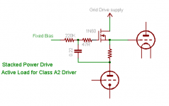
I'd like to check another idea in with you. Here's what I'm calling
stacked power drive in honor of your power drive circuit.
It's part gyrator, part follower, and has a fixed bias reference
like the power drive circuit.
I think this may be better than the series balanced drive Don
mentions above if the goal is to drive an A2.
The drive is asymmetric, as is the grid load when driving A2.
The output at the MOSFET source should be well isolated from the
driver tube, allowing the driver to operate on a flat load line.
The grid current loop is local to the MOSFET and grid drive supply.
The grid drive supply can be stacked on the power tube cathode.
It provides stable fixed bias like power drive, but presents a very
low DCR load to the driver anode (1/Gfs) + R like a choke.
I'm putting together a breadboard using this to load my
801-driving-3C24 test circuit. I'm sure it isn't new...
Cheers,
Michael
Attachments
I fixed one of Zobsky's amps with a circuit like that.
Abusing a 10M45 I think it was... Original problem:
the grid of his 12B4 kept forward conducting, and
his 12AT7 just couldn't drive into A2 without help.
His 10M45 was already there as a current sink.
I just moved the tapping upward to the top end
of the current set resistor.
The issue here is that your stacked Mu Follower
drive voltage is too high for direct G1 drive. But
might be OK for G2.
Some kind of capacitive coupling to deal with this
discrepancy before the actual superdrive, if it truly
going to be "universal". Because we skipped this
step, we never got Zob deep into A2. But even
with simple capacitive coupling, it could certainly
handle transients.
Leaning toward a triode + stacked IGBT anti-triode,
driving an IGBT superdrive, driving the output tube.
Less complicated than it sounds...
Guys, I welcome the suggestions, and I will definitely do some experiments based on some of them as time permits. I see the same issue with two of the ideas proposed. They will not generate the required drive voltages from the supplies that I have. My fault, I haven't stated the goals and requirements of this project yet, so let me do that now:
The proposal is for a "universal" driver design. What does that mean? Well to me it means a fairly simple design with the flexibility to drop in to as many different amplifier designs as possible.
I would imagine that most applications for this driver would be a typical push pull amp with 2 or 4 of the usual "audio" tubes (KT88, EL34, 6L6GC) per channel. This type of amplifier must be constructed with a single commonly available power transformer that is affordable. The common mode DC voltage level to the output tube grids will vary from 0 to -100 volts (probably a smaller range) and the AC drive requirements are moderate.
I would like to use this driver for more unusual designs like screen driven sweep tubes, conventionally driven sweep tubes and transmitting tubes like the 813. Multiple or unusual power transformers are OK here. I'm thinking two big Antek toroids. Common mode DC voltage can range from -150 volts for conventionally driven tubes to +150 volts for screen drive. The AC drive requirements are large.
Then there are the cathode follower amps. Anything goes here. Common mode DC voltages are near zero, but the AC drive requirements are HUGE. I haven't finished all of the experiments here, so the driver board may just be used to drive another driver board.
The single power transformer requirement narrows down the supply voltage choices a bit. For now lets assume that we would like to build a simple monoblock with a pair of typical audio tubes and an Allied 6K7VG or Hammond 374BX power transformer. From that transformer I can easilly get +450 volts, - 450 volts, and maybe a small positive or negative voltage from rectified filament voltage. If needed I can get a lower positive or negative voltage source using a regulator.
The original 300Beast was a fully differential design. I never exploited that feature, but I think that it would be a nice feature.
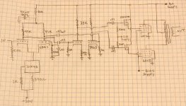
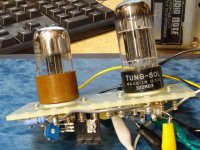
The schematic shown in a previous thread was used for a screen driven 6AV5 P-P amp. It worked quite well, but was taken apart after the experiment because I needed the breadboard for another experiment. Almost 3 years later (last summer) AES had a tube sale and I wound up with a big box full of $1, $2, and $3 sweep tubes. I needed a driver quickly, and my breadboard was in use, so I slapped together this tag board creation using octal tubes. It still functions. The circuit is pretty much the same as the one used in the 6AV5 amp. I added resistors from the mosfet sources to the negative supply. This allows the driver to be used when grid current is not drawn (conventional G1 drive). The tag board was succesfully used for screen driven sweep tubes, conventionally driven sweep tubes, and some cathode follower designs.
Some would ask why there are 2 sets of coupling caps in that schematic. Most experts believe that caps in the signal path are bad, and 4 in a single design is evil. Well, I agree! The reason for the 4 caps has to do with obtaining the maximum possible output voltage swing. For the typical KT88 type amplifier, one pair of caps can be eliminated (replaced by a jumper). There different advantages to eliminating the first or second pair, and both are still needed for high output applications.
More later......
The proposal is for a "universal" driver design. What does that mean? Well to me it means a fairly simple design with the flexibility to drop in to as many different amplifier designs as possible.
I would imagine that most applications for this driver would be a typical push pull amp with 2 or 4 of the usual "audio" tubes (KT88, EL34, 6L6GC) per channel. This type of amplifier must be constructed with a single commonly available power transformer that is affordable. The common mode DC voltage level to the output tube grids will vary from 0 to -100 volts (probably a smaller range) and the AC drive requirements are moderate.
I would like to use this driver for more unusual designs like screen driven sweep tubes, conventionally driven sweep tubes and transmitting tubes like the 813. Multiple or unusual power transformers are OK here. I'm thinking two big Antek toroids. Common mode DC voltage can range from -150 volts for conventionally driven tubes to +150 volts for screen drive. The AC drive requirements are large.
Then there are the cathode follower amps. Anything goes here. Common mode DC voltages are near zero, but the AC drive requirements are HUGE. I haven't finished all of the experiments here, so the driver board may just be used to drive another driver board.
The single power transformer requirement narrows down the supply voltage choices a bit. For now lets assume that we would like to build a simple monoblock with a pair of typical audio tubes and an Allied 6K7VG or Hammond 374BX power transformer. From that transformer I can easilly get +450 volts, - 450 volts, and maybe a small positive or negative voltage from rectified filament voltage. If needed I can get a lower positive or negative voltage source using a regulator.
The original 300Beast was a fully differential design. I never exploited that feature, but I think that it would be a nice feature.
The schematic shown in a previous thread was used for a screen driven 6AV5 P-P amp. It worked quite well, but was taken apart after the experiment because I needed the breadboard for another experiment. Almost 3 years later (last summer) AES had a tube sale and I wound up with a big box full of $1, $2, and $3 sweep tubes. I needed a driver quickly, and my breadboard was in use, so I slapped together this tag board creation using octal tubes. It still functions. The circuit is pretty much the same as the one used in the 6AV5 amp. I added resistors from the mosfet sources to the negative supply. This allows the driver to be used when grid current is not drawn (conventional G1 drive). The tag board was succesfully used for screen driven sweep tubes, conventionally driven sweep tubes, and some cathode follower designs.
Some would ask why there are 2 sets of coupling caps in that schematic. Most experts believe that caps in the signal path are bad, and 4 in a single design is evil. Well, I agree! The reason for the 4 caps has to do with obtaining the maximum possible output voltage swing. For the typical KT88 type amplifier, one pair of caps can be eliminated (replaced by a jumper). There different advantages to eliminating the first or second pair, and both are still needed for high output applications.
More later......
Attachments
I was considering starting a project that would require almost 600V pk-pk for a class AB2 amp(Unity coupled). I was thinking about it and wondered if it is really necessary to keep driving the power tube grids negative after they are cut off. If not, one could bias a 6sn7 at 8mA or so at 150V with a ccs plate load and this could swing reasonably linearly from 150 on up. One would have about 75 volts of negative swing to reach cutoff. Follow it up with a source follower and there you go. I've never done this, and I don't recall ever seeing it done elsewhere. Would it work? It almost seems too easy.
I think I remember others stating that screen driven sweep tubes are hard to turn off, so this may not be a good solution for that requirement, and it obviously wouldn't work for anything class A.
I think I remember others stating that screen driven sweep tubes are hard to turn off, so this may not be a good solution for that requirement, and it obviously wouldn't work for anything class A.
Hi George,
I see what you're after and sure, what I proposed is not very
universal, but works in place of a choke in a direct coupled stacked
driver ala "DRD".
Your universal driver ought to be capable of driving just about
anything, even loudspeakers with the right transformer ;-)
6AV5 looks good for screen drive. B+ at 300-400V?
I enjoyed the 6AV5 story, and I see those Penta 4-65As standing
by on the bench...
What I'm curious about is the coupling transformer you plan to
use. What's the DCR and voltage capability? Seems like you will
want low DCR for driving class A2. Screen drive would be less of
an issue as the mu to plate would be lower and drive current
would be more constant. Will it be a 1:1 ratio or step-down?
Cheers,
Michael
I was thinking about it and wondered if it is really necessary to keep driving the power tube grids negative after they are cut off.
I have thought about this before too, but never really tried it. I see no reason why you would need to drive a tube's grid more negative after it is cutoff, you can't make it more cutoff. If you think about it, class AB or near class B drivers are used to drive class AB outputs in the SS world all the time. Check out the inner workings of many low power opamps. It should work in the tube world as well.
I think I remember others stating that screen driven sweep tubes are hard to turn off
I don't see it that way. I have had the best results in my screen drive experiments when I apply a slight negative voltage to the control grid. This contrasts with the results of others, but it works for me. Many screen drive amps are operated on the edge of class B, the idle current is on the order of 3 to 10 mA. As the screen goes negative the tube current drops to an inconsequential value, especially if the control grid is negative. The problem with the circuit shown in post 5 is that there are no resistors from the source of the mosfets (output tube screen) to the negative supply. This didn't seem to matter much with 6AV5's but the resistors were needed when I built the tag board driver and started playing with some big sweep tubes.
6AV5 looks good for screen drive. B+ at 300-400V?
I kept getting more and more power as I increased the power supply. I was getting 80 watts out of that pair of 6AV5's at 550 volts, the limit of the power supply that I was using at the time. My new one goes to 650 volts at 1.5 amps. 550 volts is the maximum rating of a 6AV5 for those inclined to follow the ratings. When I get this driver built, I'm going to "test" a few tubes, including the 6AV5.
I enjoyed the 6AV5 story, and I see those Penta 4-65As standing by on the bench...
I had 3 of those. I was planning to "test" them after the 6AV5's but all 3 turned out to be bad. Air in all of them.
 I haven't found a Penta tube that I like yet. I have some EL34's that spark up real good, no matter what you put them in. I still have some other tasty transmitting tubes to experiment with. 813's, 811A's, 211's, 845's, 828's, and if I really want to go crazy I have a bunch of 833A's. I sold my 4-1000's though.
What I'm curious about is the coupling transformer you plan to
Transformer? We don't need no stinkin transformer! Actually I am not sure what you mean. I do not intend to have any transformers in the signal path. The amp concept does not stray too far from the schematic shown in post #5. The mosfets drive the grid directly. G1 or G2 it doesn't matter, only the drive level and the DC bias voltages change.
I built the 300Beast after experimenting with some perf board designs, and at least one prototype PC board, before laying out the driver board in the Beast. I used the Tubelab breadboarding system for my first screen drive (6AV5) experiment. I built a tag board driver for the second screen drive experiments, some conventional drive and cathode follower experiments. I now think that it is time to design a prototype driver PC board. I may even use this board to build a test amp, so I think I will make two of them.
I took the schematic from all 3 previous driver circuits, and combined them. I decided to use 9 pin miniature tubes because I have a bunch of different ones to choose from and plenty of them in case I blow one or two up. The first stage is the same in all 3 designs and I see no reason to change it.
The second stage is where the experiments need to take place. I have tried a CCS in the tail, and I have tried a big resistor to a high negative voltage. I have tried CCS's as the plate loads, and I have used resistors. This allows 4 combinations, and the only combination that I have found completely useless is CCS's in the tail and plate loads at the same time.
I have tried direct coupling between the first and second stage and found it completely suitable for lower drive voltage applications. If you look at Morgan Jones' Crystal Palace you will see that he places the coupling caps between the first and second stage, and directly couples the second stage to the cathode follower. I would like to try this approach as well. The PC board should accomodate all of the possibilities.
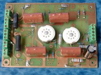
I put together an Eagle schematic for this driver on my laptop in a hospital room in Pittsburgh. I laid out the PC board at my mother in laws house in West Virginia. I finished it on Christmas day, so it was called the Christmas board. Before I ever made one of the boards, I figured out that it wouldn't work, so I did another one. This one is called the Georgia board, because I was in a hotel room there when I did that one. Yep, ditched that one too. I have finished another design that I liked well enough to actually make. It is called the Black Thursday board, because I finished it on the day that the layoffs came at work (they didn't whack me....yet).
I fabbed two of these boards, drilled one of them and started populating it. I don't have it finished yet, and I'm still missing a few parts, so it may be a while. Given all the "stuff" that has been happening, there is the possibility that it too contains an error, but I at least have the confidence to build one. I should be able to hack it up enough to make it play.
Attachments
Before I get the email asking for a schematic, here it is. The usual disclaimer applies. I haven't even built one yet. Assume that it doesn't work!
Note that there is a CCS on the tail of the second stage (IC4) there is also a resistor on the tail of the second stage (R46). Either the CCS chip OR the resistor should be used, not both. The same situation applies for the plate loads for the second stage, use the resistors (R18 and R22) or the CCS chips (IC2 and IC3). I have not been able to make the second stage work with CCS's in the plates and cathodes, all other combinations worked on the tag board.
I had the tag board working without the coupling capacitors between the first and second stages. Jumper the caps (C5 and C6) and remove R25 and R43. This raises the cathode voltage of the second stage by 100 to 120 volts. This uses up 120 volts P-P of available output drive voltage, but this is not a problem with many output tubes in conventional G1 drive, even sweep tubes.
I had plenty of time to kill while at my mother in laws house. We spent a lot of time driving to Pittsburgh and back, often daily, so I brought along a couple of books. One of my favorites, is Valve Amplifiers (third edition) by Morgan Jones. This was the third time that I have read the "meat" of that book (I skip the basic stuff at the beginning). I learn new stuff every time. While studying the Crystal Palace amplifier, I came to the realization that this driver could emulate the Palace driver if configured correctly. The coupling caps are in place between the first and second stages. The second stage has the CCS in the tail. The plate loads are resistors. The coupling caps between the second stage and the mosfets (cathode followers in the Palace) are jumpered and the bias pots removed. The grid return resistors in the second stage (R25 and R43) need to be connected to the bias pots for adjustment of the output stage bias. This was NOT tried on the tag board, and the PC board was not laid out to accomodate this, so some hacking will be needed. I may try it if I have time.
Attachments
Looking at the driver, I can't help think the 3 CSS are going to "fight", and at best be a tuning nightmare.
I understand there is a circuit for an "electronic choke" that has high AC resistance but does not impose a common current.
This would avoid the DC issues with multiple controlled currents.
Why not try the driver as a pair of common cathode amps, biased by LED?
Or substitute a center tap choke for better voltage swing. Combine that with 6s4 tubes for a very high swing driver.
Just some random thoughts from the peanut gallery.
Doug
I can't help think the 3 CSS are going to "fight", and at best be a tuning nightmare.
I assume that you are referring to the 3 CCS's that are all connected to the second stage. Yes they will fight. The result is what the digital guys refer to as a bistable circuit, or flip flop. However the text explains that there will be a CCS in the "tail" OR the pair of CCS's as the plate load, never both.
This PC board design is a "test" circuit or prototype designed to evaluate several possibilities of circuit design before deciding on the final choices. I expect that there won't be one "best design" and the configuration of the second stage may depend on the application thes the driver is used in. The only way I can be sure is to thoroughly test each combination in a controlled manner, hence the PC board where one thing can be changed at a time.
The ideal case is for the board to be wired into a test amp, and several different permutations of the circuit evaluated. Then the same board will get wired into a different amp, or the same amp with different tubes, etc, then the same evaluations performed.
Why not try the driver as a pair of common cathode amps, biased by LED?
It has been my experience that an LTP pair stage using common triode tubes will not achieve perfect balance over the entire audio range. Neither will any other phase splitter. The imperfections are slight, but adding a second differential stage is usually beneficial without needing any negative feedback. This is why I went with the LTP - SRPP stage in the 300Beast even though it was tempermental to get working and picky about which tubes I used.
Or substitute a center tap choke for better voltage swing.
I like the center tapped choke idea. I found that an LTP circuit with a tapped choke for the plate load generates a lot of linear swing, even with a 12AT7. Unfortunately these chokes aren't common.
I would like this board to eventually become the "Not so Simple P-P". This means that most of them will get used to build a KT88 P-P or 300B P-P amplifier, and they need to work all over the world with common parts. This is also the reason for the single common power transformer requirement for the basic configuration. Given these constraints, the circuit that is posted is the one that I have chosen to experiment with for the time being. It is based heavilly on some previous succesful experiments. As seen with the Simple P-P, everything is subject to change, and this may not be the final design.
Combine that with 6s4 tubes for a very high swing driver.
Tried that. The 6S4 and 12B4 do allow for some serious output swing. I found that I could get almost as much drive out of a 6SN7, and the distortion was much better with the 6SN7 at more reasonable output levels, like 50 V P-P.
I value all of these ideas, including some of the "more esoteric" ones that have been posted. They are all useful and I will get to try some of them eventually. I have been experimenting with different driver circuits for the past 2 years, and this circuit is a compromise between ultimate performance, and universal component availability. I plan to experiment with P-P drivers, and amplifiers in general even after this design is done. I have several more experiments waiting for bench time already.
Yes, you were clear on that and I flat missed it.I assume that you are referring to the 3 CCS's that are all connected to the second stage. Yes they will fight. The result is what the digital guys refer to as a bistable circuit, or flip flop. However the text explains that there will be a CCS in the "tail" OR the pair of CCS's as the plate load, never both.
Have you considered an Edcor 10K interstage with open secondaries? Or for that matter with omitted secondaries?I like the center tapped choke idea. I found that an LTP circuit with a tapped choke for the plate load generates a lot of linear swing, even with a 12AT7. Unfortunately these chokes aren't common.
That makes sense. Thanks for sharing that.Tried that. The 6S4 and 12B4 do allow for some serious output swing. I found that I could get almost as much drive out of a 6SN7, and the distortion was much better with the 6SN7 at more reasonable output levels, like 50 V P-P.
Doug
- Status
- This old topic is closed. If you want to reopen this topic, contact a moderator using the "Report Post" button.
- Home
- More Vendors...
- Tubelab
- "universal" P-P driver board