I have some 6080 valves which I would like to use in a simple-to-build yet good sounding P-P amp. I think this circuit from another thread fulfils these criteria:
http://www.excite-webtl.jp/world/english/web/?wb_url=ja1cty.servehttp.com/&wb_lp=JAEN&wb_dis=2
It uses a differential amplifier by a pair of Hi-gm of C3g. I have some hi-gm E180F pentodes which I think can replace the C3g. Is this so? As I'm not good at valve theory I would like to know what resistor changes this involves. Also, does such a circuit require a driver stage at the input in order to produce sufficient gain? I will be driving the amplifier from a separate 15-20dB linestage.
Thanks to all prospective helpers!
Best wishes and regards to all diy-ers.
Joe A
Just noticed that the link is dead. Try this one:
http://ja1cty.servehttp.com/6080/60802.html
There is an english translation of sorts from the "Return to Home Page" link.
http://ja1cty.servehttp.com/6080/60802.html
There is an english translation of sorts from the "Return to Home Page" link.
Sorry if you've been trying to access the site. I just copied and pasted the link here hoping you will be able to copy-paste it
http://ja1cty.servehttp.com/6080/60802.html
http://ja1cty.servehttp.com/6080/60802.html
Hi,
i once built a simple little 6080 PP amp with a single ended front end driving an interstage transformer to do the phase splitting. I used a suboptimal interstage which compromised the top end somewhat. If you can afford a pair of Lundahl LL1660 I highly recommend this approach.
I have been toying with the idea of a new design using a direct coupled LTP into 6080 finals, with partial feedback to drive the output impedance down.
My experience was that 6080's work extremely well at 100V and 100mA, so a split rail design with about +/-130V would do the trick. If you are interested i could lash up a schematic of my ideas. The only thing I have not decided on is what driver valve would fit the bill. It would need to work comfortably at about 100V on the plate and sinking about 1-2mA of current and a gain of about 20.
Shoog
Here is my 6AS7 amp schematic. It's 2 stage and everything runs off a single supply, so it is easy. It clips at +/- 11Vpk, so that's a little more than 7Wrms output class-A into 8ohm. It uses about 6dB of cross-coupled g2 feedback and has an output impedance of about 1ohm. I am happy with the sound. It has been the primary amp in my system for almost half a year. I plan to add some kind of DC balance for the output stage, but haven't got around to it, nor found it absolutely necessary. It could be altered to use solid state rectification or a different input transformer. Also, hammond does make a universal primary version of this power transformer.
E180F would probably work really well adapted to this design. The current project I'm bread-boarding uses E180F. I could easily adapt them to this circuit, or the one you linked to if you need help with that.
Each channel

E180F would probably work really well adapted to this design. The current project I'm bread-boarding uses E180F. I could easily adapt them to this circuit, or the one you linked to if you need help with that.
Each channel
sonata149 said:It uses a differential amplifier by a pair of Hi-gm of C3g. I have some hi-gm E180F pentodes which I think can replace the C3g. Is this so?
Joe A
A Happy New Year to Joe & all,
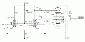
I am so glad to discuss my circuitry of 6AS7pp. Here is a modified
schematic to use E180F/6688 instead of C3g. AS you can see,
the values of resistors are identical to C3g's. The key points
are as follows:
1: Adjust 190Kohm of G2 dropper to get 200-220V for both
plates of E180F/6688.
2: Confirm G2 voltage around 100-150V after above adjustment.
Because of Hi-gm of E180F, total amplifier gain from the signal
input jack to the speaker output will be more than 30dB which
is enough to get full power(9W) of the amplifier with less than
1Vrms signal input so that you don't need to use line amplifiers.
Attachments
Hi,
Just for info, you guys my also want to dig into the forum's archives.
The PP 6080 has been discussed before and I'm positive you'll find some interesting stuff in there.
I remember one amp in particular using an ECC88 to drive a pair of 6080s which I heard on Lowthers that stuck with me. It was made in Italy and nicknamed "Topolino".
Never mind me, carry on,
Re: Re: Ideas for a simple 6080/6AS7 Push-Pull amplifier
I found similar construction amplifier in the below URL.
http://www.diyparadiso.com/sk6as7pp1.htm
The below lists comparison between mine & his.
_______________mine_______his
--------------------___-----------__-------------------
6AS7 P Voltage___160V_____170V
Differential Amp__C3g______EF86
OPT____________Custom___LL1664pp
_______________Made
Opt Imp. PP______2Kohm____3Kohm
Coupling_________Capacitor__Direct
CCS____________22Kohm___Transistor CCS
________________Resistor
According to his Web, this amplifier was exhibited
at the Paris Hi end Show.
Thank you all, guys for your suggestions. I'm still considering my options but your input has been much appreciated
Shoog wrote:
If you can I would appreciate that.
Can I ask ja2dhc and Jeb-D what is this voltage in their respective circuits (or the voltage at the cathode to ground)?
To Jeb-D
Your circuit looks nice too. Can you please work out the changes for using e180f's? Also, can you please quote the voltages at various points in the circuit for testing purposes.
Regarding the 10K:20K input transformer what type/voltage of toroidal trfx would fit in here? Judging by the results I would upgrade to the Jensen or other dedicated i/p trfx.
To: ja2dhc: In another thread you say that one can use a transistor CCS with about -15V instead of the -160V / 22Kohm bias for the LTP cathodes. As I'm not at all handy with transistors, can you please suggest a working circuit?
Thanks for your help so far.
Joe A
Shoog wrote:
I have been toying with the idea of a new design using a direct coupled LTP into 6080 finals, with partial feedback to drive the output impedance down. If you are interested i could lash up a schematic of my ideas.
If you can I would appreciate that.
My experience was that 6080's work extremely well at 100V and 100mA, so a split rail design with about +/-130V would do the trick.
Can I ask ja2dhc and Jeb-D what is this voltage in their respective circuits (or the voltage at the cathode to ground)?
To Jeb-D
E180F would probably work really well adapted to this design. The current project I'm bread-boarding uses E180F. I could easily adapt them to this circuit, or the one you linked to if you need help with that.
Your circuit looks nice too. Can you please work out the changes for using e180f's? Also, can you please quote the voltages at various points in the circuit for testing purposes.
Regarding the 10K:20K input transformer what type/voltage of toroidal trfx would fit in here? Judging by the results I would upgrade to the Jensen or other dedicated i/p trfx.
To: ja2dhc: In another thread you say that one can use a transistor CCS with about -15V instead of the -160V / 22Kohm bias for the LTP cathodes. As I'm not at all handy with transistors, can you please suggest a working circuit?
Thanks for your help so far.
Joe A
Can you please work out the changes for using e180f's?
Sure. I'll posted a schematic later today.
Also, can you please quote the voltages at various points in the circuit for testing purposes.
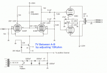
Output stage: Aprox 290V B+, Cathode bias 90V, 60mA per triode.
Driver stage is 160V plate, and 150Vg2. However, Vg2 is going to come out to a different value for E180F.
Since the circuit is class-A, The approximated loading as seen per triode:

Regarding the 10K:20K input transformer what type/voltage of toroidal trfx would fit in here? Judging by the results I would upgrade to the Jensen or other dedicated i/p trfx.
I initially specified Jensen, but used Edcor WSM10k/15K instead for the actual build. The grid resistors were changed from 10k to 7.5k. They are only $10 each, and do pretty well for line-level when terminated into the appropriate load.
You can use a toroid with a turn ratio between 1:1 - 1:2(or a 2:1 used backwards). Isolation transformers are easy to find and will work, but your source will have to be capable of delivering 2V to get full power output. If you go this route, you will want to find a transformer with a small VA rating, and you will have to play with the termination resistance to achieve good bandwidth without getting over-shoot/ringing issues. If you don't feel like tweaking with it much, I'd avoid this route.
sonata149 said:To: ja2dhc: In another thread you say that one can use a transistor CCS with about -15V instead of the -160V / 22Kohm bias for the LTP cathodes. As I'm not at all handy with transistors, can you please suggest a working circuit?
Joe A
Joe, here is what you want. It has not been tested by me, yet.
Rectifying Diodes should be more than 100V, 0.5A rated.
Transistor should be more than 50V, 100mA rated NPN transistor.
BTW, I will entry my 6AS7 amp to a contest for DIY amplifiers
in Japan in February.
Attachments
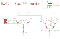
Heres what I came up with.
This design should need no adjustment as the CCS will keep everything nicely balanced.
The output stage has extremely good PSRR which means that a simple silicone diode power supply followed by a big cap should be adequate for the + rail. The negative rail should be a simple little Pi filter.
The ECC91 is a common cathode 7pin mini valve, so you have a lovely little direct coupled PP amp with just 4 valves in total.
The output transformer can be a power toroidal. I have built this exact same output stage and it works very well and is totally silent of hum. I used simple LM317 CCS originally, but the addition of direct coupling may make it neccisary to use something with a higher voltage rating. Something like a MJ350 in cascade should be simple and more than adequate.
I will be building this circuit in the summer.
Shoog
Attachments
An externally hosted image should be here but it was not working when we last tested it.
I was thinking about the design I posted and spotted one problem. You would need to incorperate a time delay on either the positive rail or both rails. This is because the 6080's will be hugely positively biased at switch on before the heaters come up. This will inevitably lead to flashovers and sudden tube death. A time delay on the positive rail is one solution, or a time delay on the center tap of the power supply mains transformer is another. This will allow problem free operation.
Shoog
Shoog
Can not understand how anyone could place the working point around and above 200+ as the 6AS7 is terribly unlinear at higher voltages.
They should not be used above 200V, but do quite well @ 200V with a 2.5k load. They are used like that in many circuits out there. Subjectively speaking, the lower voltage, higher current operation may be better. Objectively speaking, 200V operation provides slightly less distortion per given power output, and a significantly lower output impedance.
6as7 is about equally, terribly unlinear per given power output, regardless. Luckily, it is almost all even-order harmonic, so class-A PP is do-able with acceptable results.
The other main advantage of running the 6080 at 100V 100mA is that the driver only needs to develop 60V pp as opposed to well over a hundred with higher plate voltages. This makes the driver stage much easier to design and much less prone to distortion. This is important when you consider that the 6080 is likely to perform at less than unity gain.
Shoog
Shoog
Hi Shoog,
Just was on another thread considering building a 6080 PP design but with power tranny as OPT.
what impedance ratio would I need for 2 x 6080's?
Rp: 280 ohms
PP: 560 ohms?
would a 220/24v tranny work here (671:1) or do I need a higher input impedance on the primary? Like a 220/18v.
cheers
Just was on another thread considering building a 6080 PP design but with power tranny as OPT.
what impedance ratio would I need for 2 x 6080's?
Rp: 280 ohms
PP: 560 ohms?
would a 220/24v tranny work here (671:1) or do I need a higher input impedance on the primary? Like a 220/18v.
cheers
OK just finished reading :
http://www.diyaudio.com/forums/tubes-valves/76820-idea-2-tube-6080-pp-amp-18.html
but it didn't really sink in, a lot of pages.
I wasn't able to open the EI design link.
So my question about which EI tranny to go for still stands.
220v/16 or 18v maybe?
http://www.diyaudio.com/forums/tubes-valves/76820-idea-2-tube-6080-pp-amp-18.html
but it didn't really sink in, a lot of pages.
I wasn't able to open the EI design link.
So my question about which EI tranny to go for still stands.
220v/16 or 18v maybe?
- Status
- This old topic is closed. If you want to reopen this topic, contact a moderator using the "Report Post" button.
- Home
- Amplifiers
- Tubes / Valves
- Ideas for a simple 6080/6AS7 Push-Pull amplifier