Let’s say I want to run my triode (2A3-40) at 360V, -65V, and 87mA.
65V/.087= 747R…. so 750R on the cathode and where good.
BUT this never lines up on the plot sheet.
Given:
Vb=360V
Iq=87mA
U=4.2
Rp=800
Using this formula: Rk = ((Vb/Iq)-Rp) / (u+1)
Rk=641R…. so we use 650R and the plate and grid voltages all line up with the plot sheet, but now there is 100ma flowing through cathode.
So for this example, do we use 750R knowing that where running the valve at 87mA, or 650R to run the valve at the exact plate and grid voltages?
sgerus said:Let’s say I want to run my triode (2A3-40) at 360V, -65V, and 87mA.
First, you can't choose all three. If the plate voltage is 360V and the grid bias is -65V, then the idle current is going to be wherever it falls on the tube's curves.
Second, when computing load lines for single ended output stages you must be careful to remember the output load is an inductor. The actual working load line of the tube will be parallel and above the line you would use for a resistively loaded tube. This site has a good, but easy to understand writeup.
http://www.freewebs.com/valvewizard1/se.html
sgerus said:So for this example, do we use 750R knowing that where running the valve at 87mA, or 650R to run the valve at the exact plate and grid voltages?
Your plate voltage is determined by the power supply, but it can vary depending on the current load. Assuming you have designed the power supply for a given voltage at a chosen current, you will want to select the cathode resistor to deliver close to that current, and let the grid voltage fall where it may, as long as it reasonably close to the predicted value. This value will vary some from tube to tube. Depending on tube type, it can vary by as much as 20% or so. With cathode biased amps, the grid voltage and cathode current both change with the resistor, so you may have to make adjustments to the cathode resistor to get the current you want. Tube variation will make it difficult to get everything exact, so within 10% of the design spec. is fine. A closer match between channels is done by tube selection.
Sheldon
sgerus said:Let’s say I want to run my triode (2A3-40) at 360V, -65V, and 87mA.
65V/.087= 747R…. so 750R on the cathode and where good.
BUT this never lines up on the plot sheet.
Given:
Vb=360V
Iq=87mA
U=4.2
Rp=800
Using this formula: Rk = ((Vb/Iq)-Rp) / (u+1)
Rk=641R…. so we use 650R and the plate and grid voltages all line up with the plot sheet, but now there is 100ma flowing through cathode.
So for this example, do we use 750R knowing that where running the valve at 87mA, or 650R to run the valve at the exact plate and grid voltages?
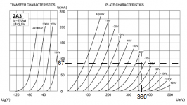
I took your first set of numbers; 360V anode-cathode, -65V and 87mA
and they do look close on the JJ 2A3-40 plate characteristics curve.
That is a valid operating point for the tube, regardless of how it was
chosen. I'd read it as -67V for 87mA and 360V.
Your first method of deriving the 65 volts across a 750R at 87mA is
correct. I don't understand why you say it doesn't line up on the plot
sheet. Did you try it like the attached example?
The other formula is incorrect for deriving the static operating point.
Mu is not a DC parameter, but dynamically derived depending on the
operating point and only assumed constant over a small delta. Same
with Rp, so can not be used to derive the DC conditions relative to zero.
Cheers,
Michael
PS as others have implied, the 360V is cathode-anode. With cathode
bias if 65V the B+ will be 425V
Attachments
 .
.Is a JJ 300b more linear than a JJ 2a3?
Here's the same OP plotted on the JJ 300b curves.
Looks a lot more linear, right?
The JJ 300b and 2a3 do in practice have identical plate characteristics,
just plotted a little differently apparently.
I guess linearity is a function of the load impedance also, but I'm
assuming some load line in the 3K5-5K range.
I guess choice of OP is also determined by the desired power output,
and the higher Va offers more Po, all other factors being equal.
With this OP you could get about 8 watts into 3K5, 6 or 7 watts into 5K.
At 250-300V you would be looking at 4-6 watts and could get nice
low distortion also.
I think another valid direction to go is treat it like a 300b and go
400V/75mA which would enable 10W Po into 3K5 and 8 watts into 5K.
The 5K loads have lower distortion at the higher operating voltages
vs 3K5 or 4K. Some folks go down to 2K5 or 3K which can work well
with some speaker types.
I also use the WE 300a/b chart to evaluate OPs for the JJ tubes.
Cheers,
Michael
Attachments
Hi Michael,
Where do you get the figures from") ? The 2A3 curves are incomplete at higher voltages so you can not get all answers from them!
? The 2A3 curves are incomplete at higher voltages so you can not get all answers from them!
Even though, you can definiately see that the 2A3s are worse at higher voltages, check -100/450V and -120V/500V as examples.
300B and 2A3 does not have identical plate characteristics, as I see it. It would have been nice to have one of each and check them in my AVO.
If wanting to go for higher voltages, 300B must be the way to go.
About JJ I would suggest measuring them before adopting them. I can not speak for 300B or their 2A3 but I started out using JJ-tetrodes when building my first series of guitar amps. Had to leave them due to inconsistency! I even ordered matched pairs from the factory but it didn´t help. A total fiasco were 3 out of 5 7591s pairs of where defective.
Where do you get the figures from
? The 2A3 curves are incomplete at higher voltages so you can not get all answers from them!Even though, you can definiately see that the 2A3s are worse at higher voltages, check -100/450V and -120V/500V as examples.
300B and 2A3 does not have identical plate characteristics, as I see it. It would have been nice to have one of each and check them in my AVO.
If wanting to go for higher voltages, 300B must be the way to go.
About JJ I would suggest measuring them before adopting them. I can not speak for 300B or their 2A3 but I started out using JJ-tetrodes when building my first series of guitar amps. Had to leave them due to inconsistency! I even ordered matched pairs from the factory but it didn´t help. A total fiasco were 3 out of 5 7591s pairs of where defective.
I get my figures on this from running both "types" in amps. I have
used them interchangeably except for the filament transformer.
I have run both JJ 2a3 and JJ 300b in the same amp at the same OP
(400V, 45-60mA range) and identical results. The samples I have
are identical except for filament voltage. The curves they publish are
different but the tubes are the same. There is a different strapping
of the filament, series in the 300b and parallel in the 2a3. That and
the color of the base...
The consistency of the samples I have (6 300bs and 2 2a3s) is
surprising to me, but then there is one bad 300b with an intermittent
anode connection. I would not hesitate to run push-pull with a 300b
on one side and a 2a3 on the other, they are even consistent across
tube number ;-)
I also had really good luck with ECC99s from JJ. The 4 samples I have
are consistent with each other and match within 1 mA side to side
with a common cathode resistor.
I haven't tried a lot of other brands yet except for NOS tubes, which
vary way more than the new JJ.
Cheers,
Michael
Attachments
sgerus said:Let’s say I want to run my triode (2A3-40) at 360V, -65V, and 87mA.
65V/.087= 747R…. so 750R on the cathode and where good.
BUT this never lines up on the plot sheet.
Given:
Vb=360V
Iq=87mA
U=4.2
Rp=800
Using this formula: Rk = ((Vb/Iq)-Rp) / (u+1)
Rk=641R…. so we use 650R and the plate and grid voltages all line up with the plot sheet, but now there is 100ma flowing through cathode.
So for this example, do we use 750R knowing that where running the valve at 87mA, or 650R to run the valve at the exact plate and grid voltages?
There's your problem. The voltage that counts is not the voltage to DC ground; but rather Vpk. If you have a Vpp= 360Vdc, and are deriving -65Vdc of bias by means of cathode bias, then your Vpk= 360 - 65= 295Vdc. You need to look at what's going on at 295V, not 360V.
I don't know why they so consistantly mislabeled that on the characteristic curves, but that's what they did. All voltages have to be referenced to the cathode and not ground.
revintage said:Great Michael,
One should have suspected the JJ 2A3 and 300B where the same tube.
Not so nice of the Slovakian guys to do fake the 2A3
I have also experienced good results with their double triodes using the ECC83(?) (bigplate) and the ECC832 in my amps.
I use the JJ300B (8yrs so far) and have encountered the JJ 2A3 which JJ bills as a 2A3 but clearly states has higher voltage and dissipation ratings than a standard 2A3 - and here is the clincher IMO it works as well or better than most 2A3 in circuits designed for the 2A3.
One thing to be aware of is that the JJ300B has a filament current requirement of 1.5A which is significantly more than the standard 300B 1.2A requirement, this would I suspect also be true of the JJ2A3 which probably requires 3A versus a usual 2A3 which requires about 2.5A. (I have not measured the JJ 2A3 filament current, but if as Michael says the difference is in filament configuration that would be the case.)
FWIW I suspect the original mono-plate 2A3 probably had plate curves that were very similar to the 300A/B. (I haven't checked)
Kevin,
I haven't measured them but the JJ spec sheets say 1.2A for the
300B and 2.5A for the 2a3. I have been running he 2a3 filaments
from 2.5V/3A hammond transformers with no heat, no buzz.
I think the actual devices are closer to the 300B, but there isn't
a lot of difference between the 300B and 2A3 characteristics in the
first place. Some time ago I went over the STC 300b curves and the
old Radiotron 2a3 curves and found only small differences. Was the
300B built to be an industrial strength 2a3 work-alike for telephony?
I tried 2a3s to replace 300b because I was at VSAC with 2 new amps
and one bad 300b. since I had the 2a3s and the filament transformers,
I figured what can I lose? Maybe have to fiddle the bias a little...
I was not too surprised when the 2a3s biased to the exact same
current in circuit as the 300bs, and performed and sounded identical.
Miles,
I believe the 360V originally quoted is meant to be p-k voltage,
which would make the B+ 425V.
Cheers,
Michael
Michael Koster said:Kevin,
I haven't measured them but the JJ spec sheets say 1.2A for the
300B and 2.5A for the 2a3. I have been running he 2a3 filaments
from 2.5V/3A hammond transformers with no heat, no buzz.
I think the actual devices are closer to the 300B, but there isn't
a lot of difference between the 300B and 2A3 characteristics in the
first place. Some time ago I went over the STC 300b curves and the
old Radiotron 2a3 curves and found only small differences. Was the
300B built to be an industrial strength 2a3 work-alike for telephony?
I tried 2a3s to replace 300b because I was at VSAC with 2 new amps
and one bad 300b. since I had the 2a3s and the filament transformers,
I figured what can I lose? Maybe have to fiddle the bias a little...
I was not too surprised when the 2a3s biased to the exact same
current in circuit as the 300bs, and performed and sounded identical.
Miles,
I believe the 360V originally quoted is meant to be p-k voltage,
which would make the B+ 425V.
Cheers,
Michael
Hi Mike,
That's Interesting because the current data sheets say 1.3A and when I had an older data sheet they definitely said 1.5A. (Unfortunately due to a recent crash I no longer have this data sheet, or at least I cannot find it. I've also referred to this value in previous posts and know I checked first before doing so.) In any event I did measure the filament current at exactly 5V on all samples (4) I had on hand at the time and it was pretty consistent at 1.45 - 1.5A at 5.00V right at the socket pins. Probably they have slightly changed the filaments since mine were made in late 2000..
I use CCS supplies to run the filaments in my 300B SE amplifier and with both sets of JJ the filament voltage is 5V +/-0.1V and the CCS are trimmed very specifically to 1.5A..
I'm wondering if they made a minor filament design tweak when they introduced the 2A3 version??

The original 2A3 and any 300B have close to the same working point when trying the "std" 2A3 Ua=250, Rk=750ohm. The 300B will just have a few mA higher Ik.
If liking the original 2A3 or 300B with 2,5V heaters is just a matter of personal taste as both are good tubes. The JJ2A3-40W will still remain a 300B with 2,5V heating.
Shame on JJ that have carbon-copied RCAs 2A3 curves together with RCAs published data(except for Pdmax, Uamax and Ikmax) in their specification sheet. They should have published the same curves and specs as in their 300B specs for the 2A3-40W.
I understand the JJ people wanting to sell more tubes with the help of 2A3s "cult" reputation. Don´t think they would have sold so many if they should have used the right name 300B-2,5V .
If liking the original 2A3 or 300B with 2,5V heaters is just a matter of personal taste as both are good tubes. The JJ2A3-40W will still remain a 300B with 2,5V heating.
Shame on JJ that have carbon-copied RCAs 2A3 curves together with RCAs published data(except for Pdmax, Uamax and Ikmax) in their specification sheet. They should have published the same curves and specs as in their 300B specs for the 2A3-40W.
I understand the JJ people wanting to sell more tubes with the help of 2A3s "cult" reputation. Don´t think they would have sold so many if they should have used the right name 300B-2,5V
.kevinkr said:
Hi Mike,
That's Interesting because the current data sheets say 1.3A and when I had an older data sheet they definitely said 1.5A. (Unfortunately due to a recent crash I no longer have this data sheet, or at least I cannot find it. I've also referred to this value in previous posts and know I checked first before doing so.) In any event I did measure the filament current at exactly 5V on all samples (4) I had on hand at the time and it was pretty consistent at 1.45 - 1.5A at 5.00V right at the socket pins. Probably they have slightly changed the filaments since mine were made in late 2000..
I use CCS supplies to run the filaments in my 300B SE amplifier and with both sets of JJ the filament voltage is 5V +/-0.1V and the CCS are trimmed very specifically to 1.5A..
I'm wondering if they made a minor filament design tweak when they introduced the 2A3 version??
Kevin, you're right. The paperwork that comes with the tube has
measurements of 1.3 or 1.4 amperes for the 6 samples of 300B
I currently have, and 2.65A for the 2A3-40s. I guess they are saying
1.3A +/- 10% which would cover 1.4 and 1.3 is within spitting distance
of 1.2 so I guess they moved the mode of the distribution
in to 1.35, rounded it down to 1.3 in the spec and had to tweak things
and give up a little emission or life or both. Maybe a new
formula for the oxide...
I'll get out the clip leads a little later and see what I have.
Michael
PS I find it interesting that popular opinion on the JJ DHT is that it's
a chameleon tube, run as a 2a3 it sounds like a 2a3 and run as a
300b it sounds like a 300b. There may be something to be learned
by that.
Michael Koster said:
Kevin, you're right. The paperwork that comes with the tube has
measurements of 1.3 or 1.4 amperes for the 6 samples of 300B
I currently have, and 2.65A for the 2A3-40s. I guess they are saying
1.3A +/- 10% which would cover 1.4 and 1.3 is within spitting distance
of 1.2 so I guess they moved the mode of the distribution
in to 1.35, rounded it down to 1.3 in the spec and had to tweak things
and give up a little emission or life or both. Maybe a new
formula for the oxide...
I'll get out the clip leads a little later and see what I have.
Michael
PS I find it interesting that popular opinion on the JJ DHT is that it's
a chameleon tube, run as a 2a3 it sounds like a 2a3 and run as a
300b it sounds like a 300b. There may be something to be learned
by that.
I think both versions of the JJ tube sound really good. So far in comparisons with a few other 300B the JJ has acquitted itself well. (Svetlana, WE, Valve Arts) In my amplifier I only find the WE300B slightly superior, and oddly enough all of that difference is in the bottom octave. I'd like to get my hands on a pair of TJ meshplates, but 400V/70mA may be a bit more than they can take... Others I know have reported similar sonic results with much newer JJ 300B than mine so I guess current production is ok..
Michael Koster said:I find it interesting that popular opinion on the JJ DHT is that it's
a chameleon tube, run as a 2a3 it sounds like a 2a3 and run as a
300b it sounds like a 300b. There may be something to be learned
by that.
I'll skip over the the perceptual pitfalls, as that seems only to apply to other people.
But, there is a physical difference that might be audible. A 2.5V filament should have less intermodulation with an AC supply, than a 5V one, all else being equal. The electrical relationship between filament, plate and cathode, would also be different for DC, reflecting the difference in the voltage gradient across the filament.
Sheldon
- Status
- This old topic is closed. If you want to reopen this topic, contact a moderator using the "Report Post" button.
- Home
- Amplifiers
- Tubes / Valves
- What is the RIGHT way to calculate the Value of the cathode resistor?