SY said:
Why do you want to decouple it? It seems to me that you want it coupled as tightly as possible.
Sorry, the magnetic coupling inside the trafo is fine. Separating the NFB keeps it from interacting adversely with the speaker load. Follow the links early in this thread to Tamura's "propaganda". FWIW, Saul Marantz used the separate NFB winding in the "storied" 8B.
My Altec 1568A has that separate winding on OPT for GNFB, too.
I've heard that this arrangement can reduce the distortion of the OPT itself, but I don't know how. GNFB right from the normal output tap is also the same as "closing the whole thing in a loop", isn't it? So what's the difference? I got a feeling that these 2 are like the comparison between autotransformer and a 'normal' one.
It's interesting that I read somewhere about SS amp design that changing the NFB from the output point to the previous driver stage could improve sound quality. The reason is not to bring back the back EMF current from the driver and mix it into the whole thing again. I've tried this in my old Hafler, the sound became loosen up, warmer, and mellower. Not bad to my ears.
Separating the NFB keeps it from interacting adversely with the speaker load.
I still don't get that. The tighter the coupling to the speaker, the more effective the feedback. A separate winding is a necessary evil if the voltage ratio from the secondary isn't correct.
I would agree with Sy on that. If you think about, unless the final stage amplification has infinite impedance, which even a pentode stage doesn't come close to, speaker counter-emf is going to haunt the output tubes. That distortion along with reactance in the speaker cables, etc are going to modulate the output tubes.
However, if you put feed those distorting emfs from the speaker back to the final amplification stage out of phase then, "in theory", you can ameliorate those bad effects. Also, using feedback to the last stage cathodes increases the damping factor just like global feedback. High damping factor is just another way of talking about controlling bad behavior of speaker. But local feedback is a much more direct and effective way of controlling the speaker than going all the way back to the front end.
It would be an interesting experiment to take separated cables from the speaker to derive the feedback rather than at the output terminals from the amp. That way you'd avoid most of the speaker cable interactions with the speaker back emf and get a purer feedback signal.
exeric said:
I would offer a couple of suggestions about nfb and the input/driver stage though. Unless the input/phase splitter/driver stage is implemented poorly 95 percent of distortion, of whatever kind you are talking about, will come from the final amplification stage. Considering this fact it might be wise to consider feedback from the OPT to the 6L6 through their cathodes. Just ignore gfb. The only requirement would be that you get an OPT with a center tapped secondary. They are defintely made and shouldn't be too hard or expensive to find. Electraprint probably makes them.
I was reading another thread here that showed that any OPT with a 4 and 16 ohm tap on the secondary is already center tapped. (How "accurate" that division of windings for the center tap is is another question.)
Just connect the 4 ohm tap to ground and use the 16 ohm and the end farthest from the 16 ohm connection back to the cathodes. Of course you'll have to do the usual math to figure if the impedance of the OPT is correct for your application.
Personally I would be mistrustful of using a transformer with 4 and 16 ohm taps for this application. These transformers weren't designed so much for center tapping as for flexibility with different speakers. In other words I wouldn't neccessarily trust that you are getting exactly equal feedback to both cathodes. An important thing to keep in mind.
Just bringing this to the top again...
I have been spending some of my precious free time going over tutorials, articles and Morgan Jones to try to understand the task ahead. I think I have come to the realisation that designing from scratch is going to be beyond my abilities, however, I would like to learn some on the way so don't really want to just copy another schematic. I have had some fantastic advice so far, but the problem for me is deciding what line/approach to take from those suggested by the 'elder statesmen' of the forum. I have no real prejudice about topology or valve complement, just that I would like to be able to use the Tamura output transformers I have. I think that they are best suited to 6L6, so am pursuing that output valve. As for the rest, I guess just about anything goes, just as long as we get good results. I am curious to follow the path of mosfet source followers, only because it is a topology I have not yet constructed and would hope to learn something.
My biggest issue at the moment is that I am travelling to LA next week and hope to have the opportunity to purchase some power transformers and have them shipped to my hotel to bring home to Australia with me. Shipping these heavy items to Australia is a killer! So, while I am flexible on topology still, some solid advice on a starting point for B+ in the next day or so would be REALLY helpful. At this stage I am thinking perhaps the Hammond 372JX, 300-0-300 250mA. That should give about 380-390 volts with a tube rectifier. Any other suggestions for specific transformers (suitable for 50Hz 240volts) gratefully accepted too.
Once again guys, thanks for the help.
Chris
I have no real prejudice about topology or valve complement, just that I would like to be able to use the Tamura output transformers I have. I think that they are best suited to 6L6, so am pursuing that output valve.
Like the 6L6, the 7591 works well in combination with your O/P "iron". Unlike the 6L6, the 7591 is very easy to drive. You could build an ABSOLUTELY killer "El Cheapo Grande" out of the Tamura trafos and 7591s.
At this stage I am thinking perhaps the Hammond 372JX, 300-0-300 250mA. That should give about 380-390 volts with a tube rectifier. Any other suggestions for specific transformers (suitable for 50Hz 240volts) gratefully accepted too.
Check the offerings of AnTek out. Prices and weight are lower than Hammond.
The best bass performance is obtained using SS rectification. So, I'd use Schottkys. If you are absolutely set on vacuum rectification, use a pair of 6AU4s.Check the offerings of AnTek out. Prices and weight are lower than Hammond...... If you are absolutely set on vacuum rectification, use a pair of 6AU4s.
I have used the Antek toroids for some of my amp experiments. They seem to work well. There is some speculation that they are actually made in China, I do not know for sure.
There are a few Antek transformers that are "made for high end tube amp", but lack the 5 volt filament winding needed for "high end tube amp."
Recently some P-P toroidal OPT's have showed up on the web site and Ebay. I don't know anyone who has tried these yet.
Last week a new Antek toroid showed up on Ebay. It is not listed on the web site yet. I think that the model # was 4TK400 but I am not sure and Ebay access is not allowed here at work. What is special about it. Well in addition to the 400 volt and 6.3 volt windings it now has a 5 volt 4 amp winding, enough juice for 2 X 5AR4's, and it features a "70 volt tap". It is not clear if the 70 volt tap is on both 400 volt windings or not. If it is, it would allow some opportunities for creative miswiring, to get 320 volts and 400 volts from the same winding. I have one on order, shipped on Monday. I probably won't get to hook it up for a week or two, but some high power P-P experiments are planned.
That particular transformer would likely be too much voltage for many 6L6 type amplifiers unless a choke input supply is used. Perhaps there will be smaller ones in the near future.
I am using a Hammond 272JX in a Tubelab SE amp. It is typical of most Hammonds that produce more voltage than the specs suggest. The 300-0-300 volt winding actually produces about 325-0-325 volts. Using a 5AR4 and a CLC filter I am getting about 365 VDC. This is a bit short of your 400 volt goal. A transformer that produces a real measured 350-0-350 or 360-0-360 volts at substantial current would be ideal for your amp (and a maxed out 300B Tubelab SE) but this seems to be absent from many vendors product line. The One Electron BFT-1B is ideal, but EXPENSIVE! I did put one of the older BFT-1's into a customers Tubelab SE a few years ago and it worked very well.
AES has "10% off of everything" until Jan 13. They have Hammond and One Electron transformers.
chrish said:So, while I am flexible on topology still, some solid advice on a starting point for B+ in the next day or so would be REALLY helpful. At this stage I am thinking perhaps the Hammond 372JX, 300-0-300 250mA. That should give about 380-390 volts with a tube rectifier.
No way! I used that very same xfmr with the 807 project I did, and I get ~365Vdc with a solid state PS (CLC ripple filter). A hollow state recitifier is going to have a lot more forward voltage. For another project using 6BQ6GTBs, I had a NOS Stancore power xfmr rated at: 650Vct @ 150mA. While the current rating was just fine, it overvolted badly with silicon diodes: 458Vdc while I needed a design value of 350Vdc. That's how the project wound up using a 5U4GB for the positive rail: between the forward drop, and voltage averaging at the first resevoir capacitor (another CLC filter, imited to 34uF to stay within the 5U4GB's 1.0A / plate Isurge rating) I got that voltage down to the required 350Vdc. You won't get 380Vdc unless you load it very light, which a 6L6 amp won't do. Of course, you can go ahead and use the Hammond. VTs are quite a bit more forgiving than is solid state, and so 350Vdc will be close enough.
Well, the Antek was waiting for me when I got home. I have good news, and bad news. First, the specs, straight off of the Ebay page:
The statement "6.3V at 5A each" implies that there are two 6.3 volt outputs, there is however, only one. This is not nearly enough filament power for all of the big ugly sweep tubes that I want to power with it. In fact just two 6LW6's is over spec. It is enough for 4 X 6L6GC and driver tubes.
There is a 70 volt tap on EACH 400 volt winding. This means that you really have a 400-70-0-70-400 volt transformer OR a 400-330-0-330-400 transformer depending on how you wire it up. This allows a wide range of possiblities for dual, tripple, and quad voltage power supplies using combinations of SS and tube rectifiers, choke and cap input filters.
Is this transformer useful for a 6L6GC? Probably, but first you need to decide what kind of 6L6GC amp you want. I plan to use this power transformer for several P-P amp experiments including some AB2 designs with 6L6GC's KT88'a and sweep tubes. This transformer can make far over 500 volts which can result in power outputs well beyond 50 watts. Using the 330 volt secondaries a B+ of about 370 volts will result which should be useful.
I don't have access to some prized Tamuras, but I did buy a flea market home built 6L6 (metal) amp about 20 years ago that had obviously never worked. I wanted it because it had a pair of UTC LS-57 OPT's that are similar in impedance and power ratings. I plan to build a "vintage" 6L6GC amp using these transformers someday. I have settled on a NOS vintage Hallordson HVPT-6 power transformer that I got at an antique store. It still has an $8 price tag on it. Specs are 350-0-350 volts at 200 mA, 5 V 3A and 6.3V 6A. Tests reveal 395 volts of B+ using a 5U4, 10 uF vintage PIO input cap and 140 mA load. I have chosen these components because they are all from the early 1960's. I plan to run the tubes in class A triode mode and take whatever power I get.
Labeled input 115 + 115 Vac (Dual coils), outputs 400Vac x 2 (dual coils) at 500mA each with 70V tap, output 6.3V at 5A each with CT and 5V at 4A. This item has CE certified.
The statement "6.3V at 5A each" implies that there are two 6.3 volt outputs, there is however, only one. This is not nearly enough filament power for all of the big ugly sweep tubes that I want to power with it. In fact just two 6LW6's is over spec. It is enough for 4 X 6L6GC and driver tubes.
There is a 70 volt tap on EACH 400 volt winding. This means that you really have a 400-70-0-70-400 volt transformer OR a 400-330-0-330-400 transformer depending on how you wire it up. This allows a wide range of possiblities for dual, tripple, and quad voltage power supplies using combinations of SS and tube rectifiers, choke and cap input filters.
Is this transformer useful for a 6L6GC? Probably, but first you need to decide what kind of 6L6GC amp you want. I plan to use this power transformer for several P-P amp experiments including some AB2 designs with 6L6GC's KT88'a and sweep tubes. This transformer can make far over 500 volts which can result in power outputs well beyond 50 watts. Using the 330 volt secondaries a B+ of about 370 volts will result which should be useful.
I don't have access to some prized Tamuras, but I did buy a flea market home built 6L6 (metal) amp about 20 years ago that had obviously never worked. I wanted it because it had a pair of UTC LS-57 OPT's that are similar in impedance and power ratings. I plan to build a "vintage" 6L6GC amp using these transformers someday. I have settled on a NOS vintage Hallordson HVPT-6 power transformer that I got at an antique store. It still has an $8 price tag on it. Specs are 350-0-350 volts at 200 mA, 5 V 3A and 6.3V 6A. Tests reveal 395 volts of B+ using a 5U4, 10 uF vintage PIO input cap and 140 mA load. I have chosen these components because they are all from the early 1960's. I plan to run the tubes in class A triode mode and take whatever power I get.
Thanks for the continuing support!
My voltage guestimate for the hammond was based on getting 480 volts from my simple se with a 375-0-375 hammond (374BX), so figured with the same line voltage and similar hammond over voltage issues I would get around 380-90 volts with the 300-0-300 transformer...
After seeing Eli's post, I had a brief look to see what I could find regarding the 7591. From what I can see, it looks kind of like a more refined, easier to drive 6L6 type? The 7951 data sheet states that ultra linear AB1 with fixed bias B+400 volts there should be about 32 watts with 1% distortion in to a 6600 load. That looks like it might be in the right ball park for the Tamura transformers, at 6600 and 30 watts. If the 7591 is a better audio tube, then perhaps this is worth pursuing. The voltage requirements look to be similar to that required by a 6L6 design too, so perhaps I figure on a 400-425 volt B+. Now, the issue is that I will need a transformer with about 330 volts if I want valve rectification, 300 without? There is an Antek 280mA toroid that has 2 x 350 secondaries and 2 x 6.3 4A secondaries. With the suggested 6AU4 6.6volt damper diodes, this combo might be workable. Price is right, but unless I can find something to hide them, I think I would rather go with the classic tube style.
Any further input welcome!
Cheers,
Chris
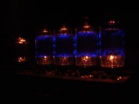
I have a 7591 amp. The cool thing about the 7591s is that most have a blue glow on the inside of the glass. The ones in the picture are EH 7591s.
I just switched my B+ for my power tubes on my amp from a CLC filter to a maida regulator (0-500mA). The difference was not subtle. The amp sounds much more powerful with that stiff supply. If you are not put off by a little extra complexity, you might want to consider a Hammond 378CX or 300BX and you can set the B+ to whatever you like just by changing a resistor in the regulator. I would share a schematic if you are interested.
I just switched my B+ for my power tubes on my amp from a CLC filter to a maida regulator (0-500mA). The difference was not subtle. The amp sounds much more powerful with that stiff supply. If you are not put off by a little extra complexity, you might want to consider a Hammond 378CX or 300BX and you can set the B+ to whatever you like just by changing a resistor in the regulator. I would share a schematic if you are interested.
Attachments
Chris,
The 7591 is a very nice tube. Back in the days of yore, Fisher and Scott got an awful lot of milage out of the type. The thing you must be aware of is that current production EH 7591s are utterly unforgiving of liberties being taken with grid leak resistor limits. Much of what the circuitry ends up looking like is affected by that fact. I strongly favor the use of combination bias in 7591 scratch builds. Doing so allows the grid leak resistor value to be safely pushed up. Keeping the grid leak resistor value up maintains the gain of the prior stage.
An easy way to deal with a toroid's wretched cosmetics is to mount it "below decks". Your Tamura O/P trafos are definitely creme de la creme. IMO, you should go "whole hog" in your build. Select a power trafo that will yield about 430 V. working into a choke I/P filter. Using 6AU4s for rectification should yield approx. 0.85 of the AC RMS value. The MASSIVE Hammond 193Q is a potential selection for use as the 1st inductor in a choke I/P supply. The very, very, slow start of damper diodes is particularly beneficial, when choke I/P filtration is employed. A bleeder resistor to ensure the draw of critical current is not needed.
OK, I think we are now talking!
To go full choke input, we are talking about 500 volts on the secondary. To do that I would have to go toroid. I don't have the space under the chassis for that. 400 is about the best there is in the Hammond range. I like the idea of going "all out", but I think there will have to some practical limitations. I have managed to accumulate a little pile of parts, including the Tamura output transformers, before moving in with my partner. I did this knowing that after we are together I would have to justify major expenditure. That 193M choke is HUGE! 21lbs! As I am building monoblocks, that would quickly blow my baggage allowance flying home! Would a suitable compromise be to go with a 400 volt Hammond such as the 378X (400-0-400 200mA) or 300BX (400-0-400 250mA), the smaller 193Q choke (10H 300mA) and then use a small input cap to adjust B+? Had a brief look at PSUII, and it shows about 5uF on the input should give around 420 volts.
I am also limited by chassis size. I picked up a pair of nice alu chassis from Singapore last year. They are 230mm wide, 360mm deep and 60mm high (9" x 14" x 2.3"). Here is a link
SpreadSpectrum's suggestion for a regulated B+ may be interesting too. If the drive requirements of the output valves are simpler than 6L6, then perhaps some effort/chassis space on regulation might be interesting?
Also, if I am going to order transformers in the next day or so to save shipping, then perhaps I should look at ordering the other valves too. Damper diodes look cheap at AES and they have the 7591 in JJ and EH flavours. Any preference for brand here?
Since you mentioned El Cheapo Grande, any hints on topology? Would a simple 12AT7 LTP with CCS tail be enough drive? Excuse my ignorance, but the data sheet lists the 'peak AF grid to grid voltage 42 volts'. Is this the drive requirement? If so, does this push the drive capability of a 12AT7 LTP, as I think I recall that a LTP only gives about half the amplification factor per output compared to a single common cathode amplifier.
Sorry for the dumb questions, but thanks again for the help!
Chris
To go full choke input, we are talking about 500 volts on the secondary. To do that I would have to go toroid. I don't have the space under the chassis for that. 400 is about the best there is in the Hammond range. I like the idea of going "all out", but I think there will have to some practical limitations. I have managed to accumulate a little pile of parts, including the Tamura output transformers, before moving in with my partner. I did this knowing that after we are together I would have to justify major expenditure. That 193M choke is HUGE! 21lbs! As I am building monoblocks, that would quickly blow my baggage allowance flying home! Would a suitable compromise be to go with a 400 volt Hammond such as the 378X (400-0-400 200mA) or 300BX (400-0-400 250mA), the smaller 193Q choke (10H 300mA) and then use a small input cap to adjust B+? Had a brief look at PSUII, and it shows about 5uF on the input should give around 420 volts.
I am also limited by chassis size. I picked up a pair of nice alu chassis from Singapore last year. They are 230mm wide, 360mm deep and 60mm high (9" x 14" x 2.3"). Here is a link
An externally hosted image should be here but it was not working when we last tested it.
SpreadSpectrum's suggestion for a regulated B+ may be interesting too. If the drive requirements of the output valves are simpler than 6L6, then perhaps some effort/chassis space on regulation might be interesting?
Also, if I am going to order transformers in the next day or so to save shipping, then perhaps I should look at ordering the other valves too. Damper diodes look cheap at AES and they have the 7591 in JJ and EH flavours. Any preference for brand here?
Since you mentioned El Cheapo Grande, any hints on topology? Would a simple 12AT7 LTP with CCS tail be enough drive? Excuse my ignorance, but the data sheet lists the 'peak AF grid to grid voltage 42 volts'. Is this the drive requirement? If so, does this push the drive capability of a 12AT7 LTP, as I think I recall that a LTP only gives about half the amplification factor per output compared to a single common cathode amplifier.
Sorry for the dumb questions, but thanks again for the help!
Chris
If so, does this push the drive capability of a 12AT7 LTP
As an LTP, you're likely to get a gain of about 20 per side. You need 21V per side peak to drive the output stage. Going back to RMS, that's an input sensitivity of 0.7V.
Now, if you use cathode feedback around the output stage, you're likely to have to swing more like 33V per side, which is doable, but pushing things (I'd want to use something different than a 12AT7 there).
If you use overall loop feedback instead and reduce the input sensitivity to 2.8V (within the capability of many good preamps), you've got room for 12dB of feedback and can certainly use the 12AT7.
Thanks for the input Sy.
As for input sensitivity, I will be running these as the amps of my main speakers downstream of an active crossover (set at 80Hz for stereo woofer units). I am not exactly sure what level of adjustability there is in the design, so would prefer it to have a fairly 'standard' sensitivity.
Thanks,
Chris
If you do go with a regulator, don't forget to allocate room for the heatsink. Other than that, they don't take much space. Much cheaper and smaller than a choke.
I use this heatsink. You could hide it on the back of the amp behind a power transformer, but it would stick up (or down) a bit. This heatsink gets warm to the touch pulling 210mA at idle(dissipating 15W or so in the regulator). If you are building monoblocks, you could probably get away with a smaller heatsink.
I use this heatsink. You could hide it on the back of the amp behind a power transformer, but it would stick up (or down) a bit. This heatsink gets warm to the touch pulling 210mA at idle(dissipating 15W or so in the regulator). If you are building monoblocks, you could probably get away with a smaller heatsink.
Thanks.
Do you think you could post the schematic for your regulator?
As for heat sinking, the chassis is solid aluminium plate, perhaps using the chassis as a sink would be OK?
Any further input as to the power transformers? 300BX is 250mA, 378X is 200mA. Interestingly, the BX is $7 cheaper at AES... I have to finalise my transformer and choke choice by tonight (Sydney time) if I am to get it delivered in time.
Thanks again guys, really appreciate the assistance and suggestions so far.
Chris
- Status
- This old topic is closed. If you want to reopen this topic, contact a moderator using the "Report Post" button.
- Home
- Amplifiers
- Tubes / Valves
- 6L6GC AB2 Amp