I use them in "grid as plate" mode: the grids are to be connected to AC and the plates left alone (do not touch them... hi-volts are anyway present!). Pretty simple. You do need to cook them for 1 hour (fils on, AC off) before the first "ignition"; and 30secs - 1min when used daily. If they do not ignite or are prone to arc over just replace them (or try lowering the AC voltage in case of arcs).
Mind the max voltage! They can withstand lower AC this way. I use WE394As and they can go up to 300-350VAC grid-to-cathode. You need bigger thyratrons for higher voltages
Gianluca
Mind the max voltage! They can withstand lower AC this way. I use WE394As and they can go up to 300-350VAC grid-to-cathode. You need bigger thyratrons for higher voltages
Gianluca

A blue glow (as all the mercury recfiers). The bird cage let the filament shine through. Lovely, isn't it? Some do not have the bird cage but a closed plate.
http://www.paolopoli.it/Audio/Bottom2008/img_1042.jpg
http://www.paolopoli.it/Audio/Bottom2008/img_1042.jpg
JoshK said:Wow, those are beauts!
Somehow I was thinking Thyratrons were another type of gas, not mercury and glowed purple. Never experimented with this stuff before.
thanks for asking this letter....
yes - mercury is glowing very, very nice.... heheheheh
JoshK said:I think it might be Ardon that glows purple. Thyratrons is a general category for gas filled tubes, no?
No Thyratron = gas filled triode, generally used for the same sorts of applications where we today use SCR and triacs. (Power control)
Some small thyratrons were also used in relaxation oscillator circuits and the like.
Ciao
I am using them in my 211 preamp. I believe I am drawing something around 50-60mA. Its a full bridge (thyratrons + solid state diodes) to get 500VDC out of a 300+300VAC transformers.
Thyratrons need many amperes for the filaments. If my memory doesn't fail, 394A filament runs at 3.5A. The bigger 355As and 354As a whopping 15A!
Gianluca
kevinkr said:have you tried tying grid and plate together?
Hum ... no. Should I?
thanks guys for any info...
i have found somewhere this schematic for half wave manually controled rectifier.......
the left transformer is clear - high voltage...
the one in the middle also - heating of the tube....
but the oneon the right is not very clear to me......what's he used for.....
and also - that variable capacitor - what is he used for and how to tune it - to what to tune it.....
Attachments
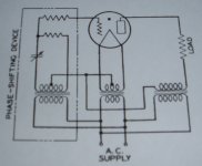
coresta said:Hi , this is the heart of the systeml . The variable condenser will change the slope of the sinus voltage fed to the grid and thus change the conducting time of the conducting periode of the gas ... exactly the same as an halogen lamp fed by a variable triac "variator"")
Coresta is dead right, the left hand transformer provides the grid voltage for firing the tube each half cycle, the phase shift network changes the firing angle so that the half wave output can be "chopped" to vary duty cycle and hence effective power into the load, and the right hand transformer provides the voltage to the load. This is basically a half wave lamp dimmer..

I am not sure whether or not grid and plate should be tied together, I'm just wondering about the dissipation rating of the grid, you are using it in ways for which it was not intended.
With the 394A, as Gianluca mentioned using the grid solo drops the PIV from 1250V to around 350V. Tying the grid to the plate, doesn't alter the PIV but it does shift the blue glow up a bit. Sound wise I could not hear a difference between the two connections. In the case of the thyratrons in question, the grid is much larger than the plate so dissipation isn't an issue.
If you need to get more than the 350V from the 394, you need to limit the current to the grid and I found that a 1K resistor from grid to plate allowed me to go upwards of 600V where I ran out of rotation on my variac. I do think I noticed a change in sound when run this way an I'd be interested if Ginluca would try the different configurations and report back.
dave
- Status
- This old topic is closed. If you want to reopen this topic, contact a moderator using the "Report Post" button.
- Home
- Amplifiers
- Tubes / Valves
- thyratron rectifier