Hello all,
I'm a newbie & currently building my tube pre-amp.
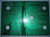
Some people say it's cloned from Marantz-7 preamp,
but I don't know exactly (PCB picture is attached).
I got the PCB & all the components as a "gift" &
the paper that I have on it just the part list
(without the schematic or further explanation).
Later, by browsing I found the schematic but less
of information about constructing it.
1. I need some helps/info about the final step of
constructing it since I never done tube preamp.
What things should I care for?
2. What is the use of VR1 on the PSU section or when we "use" it?
3. How should I connect all the GROUND/EARTH cables
to prevent or at least reduce the noise/hiss?
4. I use the R-Core transformer type, do I need to
add Soft-Start Circuit for this type transformer?
I would really appreciate for any answer/help.
Thanks.
I'm a newbie & currently building my tube pre-amp.
Some people say it's cloned from Marantz-7 preamp,
but I don't know exactly (PCB picture is attached).
I got the PCB & all the components as a "gift" &
the paper that I have on it just the part list
(without the schematic or further explanation).
Later, by browsing I found the schematic but less
of information about constructing it.
1. I need some helps/info about the final step of
constructing it since I never done tube preamp.
What things should I care for?
2. What is the use of VR1 on the PSU section or when we "use" it?
3. How should I connect all the GROUND/EARTH cables
to prevent or at least reduce the noise/hiss?
4. I use the R-Core transformer type, do I need to
add Soft-Start Circuit for this type transformer?
I would really appreciate for any answer/help.
Thanks.
Attachments
Hi Cruzs,
Your preamp is very similar to the line section of a Marantz 7. The slight difference is that the Marantz uses all 12AX7s, no 12AU7s as you can see here.
The purpose of VR1 in the power supply regulator is to adjust the output voltage. Probably by a limited amount just to trim the level.
Generally all of the ground connections should be joined together at one spot on the chassis. Assuming you are mounting the PCB on a chassis. This is called a "single point ground". Exactly where that single point should be is best found by experimenting. Sometimes near the input works best. Sometimes it's best to be centrally located, or near the power supply. Whatever gives the lowest hum level is the proper place.
I'm not exactly sure what an R-core transformer is, but since this is only a preamp (with no big output tubes) no soft start is necessary. It also appears that the PSU in the center of the diagram is some kind of delayed relay power. Possibily to prevent turn-on thump. But it's unclear what the relays connect to. Prehaps the output of the preamp signal.
The lower PSU is the filament supply.
Edit: Looking at the PC board it may be that the power supply is seperate from the signal section. (not sure) Connections netween the two may be necessary. I would suggest contacting the manufacturer for the instruction sheet that was normally supplied....if any.
Victor
So I have to trim VR1 to adjust the output voltage for 280VDC~300VDC, am I right?
Just to make it clear for me and maybe for my own safety factor,
(it sounds like a silly question) when I trimming VR1 for the output voltage all 3 tubes of the PreAmp section should be on their places on the board, am I right? as a beginner I prevent
to make any failure/mistake during the setting stage and this thing, it uses high voltage (I am afraid to blown any component for the silly mistake).
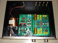
Thanks Victor.. your answers (really) help me. Any other thing or information that I should care about my project?
BTW, I attached my semi-completed PreAmp tube.
And again.. feel free to comment or give opinions.
Just to make it clear for me and maybe for my own safety factor,
(it sounds like a silly question) when I trimming VR1 for the output voltage all 3 tubes of the PreAmp section should be on their places on the board, am I right? as a beginner I prevent
to make any failure/mistake during the setting stage and this thing, it uses high voltage (I am afraid to blown any component for the silly mistake).
Thanks Victor.. your answers (really) help me. Any other thing or information that I should care about my project?
BTW, I attached my semi-completed PreAmp tube.
And again.. feel free to comment or give opinions.
Attachments
Cruzs said:So I have to trim VR1 to adjust the output voltage for 280VDC~300VDC, am I right?
Just to make it clear for me and maybe for my own safety factor,
(it sounds like a silly question) when I trimming VR1 for the output voltage all 3 tubes of the PreAmp section should be on their places on the board, am I right?
Yes, that is how I would do it. Although if the regulator is correctly designed it shouldn't matter if it's under load or not. Plus, the actual voltage output is not that critical so long as it's within that range.
One thing I would do that's very important is to put a fuse in the primary of your power transformer to protect it and the rest of the circuit. I'd use no more then 1 amp and maybe less depending on final currnt draw.
I have that exact same board. I got it pre assembled. I thought it came as a kit but it came already filled.
I am having one issue if you notice on the board there is two connections for 6.3. The transformer I got only has one 6.3 output. Do I just run another line over and run these connections in parallel?
my pri is labeled
with 2 115v
red-----
|
yel------
grn-----
|
org-----
I take it i need to attach trhese in parallel. red & grn and yel & org.
The secondary is
300 yel
0 org
300 yel
18 brn
18 brn
18 gry
18 gry
12.6 blu
12.6 blu
6.3 wht
6.3 wht
billbeau said:
my pri is labeled with 2 115v
red-----
|
yel------
grn-----
|
org-----
I take it i need to attach trhese in parallel. red & grn and yel & org.
Since I am unfamiliar with your board and how it is configured, So I won't comment on the 6.3 volt needs.
Regarding the primary you are right but, unless you are sure of the phasing and color coding, I would connect a 60 watt light bulb in series with the paralleled windings just to be safe. If it's correct, the bulb should not light very much if at all with secondaries disconnected. If it lights up brightly, reverse the phases. I've learned to not always trust the coding, especially if it's a newer import.
Interesting. The schematic on the tranny shows the dots for the primary. The red and the green have the phase dots. I was going to connect these two together.
The schematic for thwe board can be found here
http://www.kitsparts.com/shop/download/audio/schematic_pdf/LS7b_M7.pdf
A picture of the tranny is here.
http://www.kitsparts.com/shop/index.php?main_page=product_info&cPath=1_110&products_id=339
Parts list for the board is here.
http://www.kitsparts.com/shop/download/audio/partslist/m7%20la.htm
- Status
- This old topic is closed. If you want to reopen this topic, contact a moderator using the "Report Post" button.
- Home
- Amplifiers
- Tubes / Valves
- A newbie need helps on the very 1st tube PreAmp