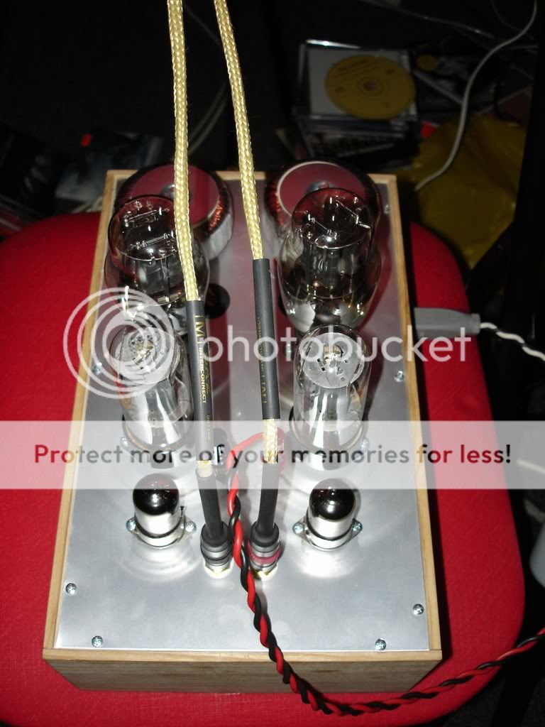
Hoktuna is now playing the proto he built of my SETOR with great success. He reports an "amazing soundstage"!
I have for a long time been thinking of building a DD for my ML Script panels. I have even let Jack at Electra-Print wind me a pair of PP-chokes.
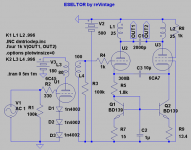
Why not unwind the secondaries of a 30VA to use as PP-choke in this configuration? A 6CA7 or 6550 could easily be arranged as opposing element to a 300B. A Lundahl LL1660/18mA as IT.
I have for a long time been thinking of building a DD for my ML Script panels. I have even let Jack at Electra-Print wind me a pair of PP-chokes.
Why not unwind the secondaries of a 30VA to use as PP-choke in this configuration? A 6CA7 or 6550 could easily be arranged as opposing element to a 300B. A Lundahl LL1660/18mA as IT.
Attachments
One area that still concerns me, is PSRR. The power
supply here might need to be awfully clean. 120Hz
ripple is within the passband for differential mode.
Noise currents will be carried entirely by the Triode
side, and double trouble when the Anti-triode tries
to anti-copy them?
I am still thinking along the lines of letting the brute
bridge float on the current sources, and track B+ by
means of ultrapaths for the Anti-Triode's reference(s)
screen and grid bypass to b+ rather than ground.
The input stage might then float the signal up to a
common noise by means of Transformer, Loftin White,
or high impedance voltage-variable current source
(Sand, Pentode, or Cascode).
High PSRR might be achieved without the need for
excessive filtering of B+.
---------------------------------------------------------------
Also keep in mind the input can be made at either
Triode or Anti-Triode, inverted result has the same
tri-ody single-endedness. The Pentode might have
less Plate-Grid capacitive losses to drive than the
Triode.
kenpeter said:One area that still concerns me, is PSRR. The power
supply here might need to be awfully clean. 120Hz
ripple is within the passband for differential mode.
Noise currents will be carried entirely by the Triode
side, and double trouble when the Anti-triode tries
to anti-copy them?
The power supply noise is coupled through the Rp/Rk divider
and transmitted to the anti-triode in an additive way. I'm working
on some ideas to deal with it, but double the hum has not been
a huge issue for me with 94db/W speakers. My B+ ripple is
about 100mV if I recall correctly and I get about 3mV at the
output, but that's with a mu of 6 and a 10K:8ohm OPT.
I thought it would be easiest to use a variation of the LW noise
balancing techniques and feed an anti-noise signal into the
signal mirror side directly using a cap (similar to cap-coupling
PS noise to the driver cathode which would also work, right?)
Of course, I have the opamp circuit which makes it simple to
inject a controlled amount of noise into the anti-side. There
will be a way...
Michael
PS by my calculations the ripple at the output should be 5mV for
100mV on the B+
Thats a great idea!
With a Mu of 6, inject 1/6 PSRipple into the antitriode's grid.
Or the other way round if anti-driving from the dark side of
the listening glass...
The Triode's plate will then be common mode noise with B+,
anti-triode's differential misbehavior automagically corrected.
With a Mu of 6, inject 1/6 PSRipple into the antitriode's grid.
Or the other way round if anti-driving from the dark side of
the listening glass...
The Triode's plate will then be common mode noise with B+,
anti-triode's differential misbehavior automagically corrected.
I dunno, cause a pair of really good 220uF at that voltage
is a bit large and possibly expensive? A circuit with inherent
noise cancellation/immunity usually involves smaller caps.
Possibly caps made for audio rather than motor run?
Cause 440uF and 3 Henries can store dangerous amounts
of energy, far more than needed to carry the amp through?
Once a fuse blows, I want the amp to stop immediately.
Cause chokes are resistive and also have hysteresis not
accounted for in sims? Need another lump of mystery iron
like I need a hole in the head...
A really smooth power supply isn't a bad thing to have,
its just maybe not as necessary as some people think.
Its entirely possible to abuse BOTH approaches for a
really really quiet amp.
In circumstance where the sum of both branch currents (class A)
is held to a constant, what is to be seen modulated onto the
ripple? Only those losses due hysteresis, or delivered into the
actual load... What does that have to do with a circuit immune
to care of such variances as they might appear on the B+?
is held to a constant, what is to be seen modulated onto the
ripple? Only those losses due hysteresis, or delivered into the
actual load... What does that have to do with a circuit immune
to care of such variances as they might appear on the B+?
Mu, Gm, Rp depend on a plate voltage.
Why don't spend one MOSFET ?
R-C with high time constant on a gate, one gate stopper, one Zener to protect the gate, and one more optional resistor in drain to protect against an overcurrent. A huge ripple reduction for expense of only 3V of a loss.
Why don't spend one MOSFET ?
R-C with high time constant on a gate, one gate stopper, one Zener to protect the gate, and one more optional resistor in drain to protect against an overcurrent. A huge ripple reduction for expense of only 3V of a loss.
How come you guys are talking about modulation of a 120Hz signal in a thread I started about an amp for mid that is crossed over 2 octaves higher") ?
?
But I understand your interest in the "assymetrical self-split" with toroids(or 6B4G SE on steroids). Hoktunas reports are encouraging. For the proto he used an old PSU with 6D22, LC 15H 20uF filtering.
Also in a lowbudget project like this it is OK with electrolytics, no need for motorruns here. Or we could maybe get away with smaller caps and CLCLC. Hammonds are cheap......
kenpeter: You are a true audio-poet ! For a Swede it isn´t always so easy to follow your turns  .
.
?But I understand your interest in the "assymetrical self-split" with toroids(or 6B4G SE on steroids). Hoktunas reports are encouraging. For the proto he used an old PSU with 6D22, LC 15H 20uF filtering.
Also in a lowbudget project like this it is OK with electrolytics, no need for motorruns here. Or we could maybe get away with smaller caps and CLCLC. Hammonds are cheap......
kenpeter: You are a true audio-poet
! For a Swede it isn´t always so easy to follow your turns .Wavebourn said:Mu, Gm, Rp depend on a plate voltage.
Why don't spend one MOSFET ?
R-C with high time constant on a gate, one gate stopper, one Zener to protect the gate, and one more optional resistor in drain to protect against an overcurrent. A huge ripple reduction for expense of only 3V of a loss.
Gyrator is good.
kenpeter said:
Gyrator is good.
Yes, but I meant a source follower.
revintage said:How come you guys are talking about modulation of a 120Hz signal in a thread I started about an amp for mid that is crossed over 2 octaves higher
...
PSRR is one characteristic of this design that needs improvement.
Your approach is reduce the ripple, which will work fine.
I guess if you HPF the input at 500 Hz then you don't need to
worry even about modulation with the 120 Hz. Or will the
nonlinearity of the transfer function cause the 120 and >500 Hz
to be partially multiplied, producing sideband frequencies at large
signal amplitudes?
Great idea to use the toroid above 60 Hz. There should be much
less saturation and you can get closer to the core's power rating.
On the original topic, I think it will work as a differential choke
as well as an OPT, within the limits if low frequency saturation.
As such, the DCR may be less of an issue than with an OPT.
Michael
Hi Wavebourn,
Please show us schematics of your previous design for as this must be a help on the way. But you are absolutely on the right track: To reduce ripple from the PSU=fix the problem at the source.
The purpose with this thread was the ESLDD without secondaries and with the toroids CT to ground! Have not seen so much comments or concerns about that except in Michael last thread.
revintage said:Aha
The ML Script has an ESL-panel that is crossed over at 500Hz and has a capacitance of ca 2000p.
I finally figured that out, but is wasn't obvious about the 500Hz
unless you know ESLs.
Now the thing I would check with this, is what slew rate your design
can drive into 2nF. It looks like it takes 70mA of peak signal current
to drive the 2nF with a 560V P-P sine wave at 20KHz. This is an
equivalent slew rate of 35V/uS. But I don't know much about ESLs
and what else you need to consider. Is there compensation of the
frequency response or does constant drive voltage over frequency
produce a flat response?
Anatoliy, are you proposing a source follower in the B+ as a
voltage regulator? Should work fine, but I think the voltage
drop would be 3V minimum at the lowest line voltage, increasing
as line voltage is increased. I'll need to try this sometime for B+
regulation.
Michael
Michael,
Hopefully and probably signal levels of that magnitude will never be present at 20k although up to 5k. I do not think there will be a problem. Must try this anyway!
About the SETOR, I will try another cathode arrangement that lowers distortion considerably when simmed.
As I understand it Wavebourns proposal is not so much for regulation as ut for reducing ripple with a MOSFET gyrator.
Hopefully and probably signal levels of that magnitude will never be present at 20k although up to 5k. I do not think there will be a problem. Must try this anyway
!About the SETOR, I will try another cathode arrangement that lowers distortion considerably when simmed.
As I understand it Wavebourns proposal is not so much for regulation as ut for reducing ripple with a MOSFET gyrator.
revintage said:Hi Wavebourn,
Please show us schematics of your previous design for as this must be a help on the way. But you are absolutely on the right track: To reduce ripple from the PSU=fix the problem at the source.
It was discussed here already on the forum: Alligator project. The main idea is, to use feed-forward only approach on AC, so 2 independent shoulder are counter-modulated, where one is a tube, and another is a modulated SS CCS. Servo makes an average current supplied by CCS equal to the current supplied by a tube, to make a transformer happy.
Michael Koster said:
Anatoliy, are you proposing a source follower in the B+ as a
voltage regulator? Should work fine, but I think the voltage
drop would be 3V minimum at the lowest line voltage, increasing
as line voltage is increased. I'll need to try this sometime for B+
regulation.
Yes, I got rid of ripples such a way of 800V supply in Pyramid-V amplifier after seeing what happens on a power: couple of sidebands, 40 dB down from the fundamental. I did not measure after, but sonically it is more crystal - clean now. The DC voltage drop is about 3V, and nearly independent on current and voltage.
- Status
- This old topic is closed. If you want to reopen this topic, contact a moderator using the "Report Post" button.
- Home
- Amplifiers
- Tubes / Valves
- ESLDD with "anti-triode"