Hi guys,
i want to learn about how to build psu using tube rectifier. particulary 5AR4 as this drop the least voltage.
can you please guide me to the link or information on the schematic or wiring diagram of tube rectified psu full wave? how to wire the pins?
how to wire the filament using the 5v? from my research this 5ar4 is claimed to be half indirect heated? whats that mean? how to wire it?
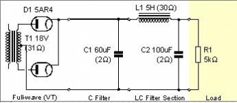
i played around with duncan psud II and here is roughly what i can come up with. but still need advice on wiring.
some advice on which tube rectifier to experiment that can give me more option to use different kind of tubes is really appriciated
thanks in advance,
Erwin
i want to learn about how to build psu using tube rectifier. particulary 5AR4 as this drop the least voltage.
can you please guide me to the link or information on the schematic or wiring diagram of tube rectified psu full wave? how to wire the pins?
how to wire the filament using the 5v? from my research this 5ar4 is claimed to be half indirect heated? whats that mean? how to wire it?
i played around with duncan psud II and here is roughly what i can come up with. but still need advice on wiring.
some advice on which tube rectifier to experiment that can give me more option to use different kind of tubes is really appriciated
thanks in advance,
Erwin
Attachments
Thx sarrisk. thats quick.
i got questions:
1. can i try this setup on the 18v tranformer that can power my diy DAC? it need around 18v to 24v. as a replacement of solid state rectifiers bridge?
2. is choke only being use for tube rectifer or any psu setup with solid state rectifier? why most diagram i saw is only CRC in ss psu? cost factor?
3. the link is for 5U4, is this the same wiring for 5AR4?
sorry bout newbie questions. thanks a lot for the help
referencing:
http://www.mif.pg.gda.pl/homepages/frank/sheets/093/5/5AR4.pdf
is my pin wiring picture below taken from sarris.info is correct? thx
http://www.mif.pg.gda.pl/homepages/frank/sheets/093/5/5AR4.pdf
is my pin wiring picture below taken from sarris.info is correct? thx
Attachments
is my pin wiring picture below taken from sarris.info is correct
Yes, except that you have interrupted the lead going from the heater to pin 2...
milen007 said:Thx sarrisk. thats quick.
i got questions:
1. can i try this setup on the 18v tranformer that can power my diy DAC? it need around 18v to 24v. as a replacement of solid state rectifiers bridge?
2. is choke only being use for tube rectifer or any psu setup with solid state rectifier? why most diagram i saw is only CRC in ss psu? cost factor?
3. the link is for 5U4, is this the same wiring for 5AR4?
sorry bout newbie questions. thanks a lot for the help
hmmm... ok
You need something little bit different.. Ok be patient to draw something exactly for your needs, and to post it here.
regards
costas
milen007 said:Thx sarrisk. thats quick.
i got questions:
1. can i try this setup on the 18v tranformer that can power my diy DAC? it need around 18v to 24v. as a replacement of solid state rectifiers bridge?
2. is choke only being use for tube rectifer or any psu setup with solid state rectifier? why most diagram i saw is only CRC in ss psu? cost factor?
3. the link is for 5U4, is this the same wiring for 5AR4?
sorry bout newbie questions. thanks a lot for the help
You're not planning on using the 5AR4 to rectify 18V are you? Tube rectifiers are not a suitable choice for very low voltage high current supplies used in most solid state designs although I have heard of a few people attempting to do this with varying degrees of success.
Tube rectifiers all have much higher voltage drops at a given current than a solid state rectifier and generally much lower peak current and continuous current ratings as well. A 5AR4 has a maximum current rating of around 250mA and will drop at least 20V - 25V at this current level.
Hopefully I have misunderstood you.
Hi Costassarrisk said:
hmmm... ok
You need something little bit different.. Ok be patient to draw something exactly for your needs, and to post it here.
regards
costas
Thanks for doing that, would love it. thx in adv
kevinkr said:
You're not planning on using the 5AR4 to rectify 18V are you? Tube rectifiers are not a suitable choice for very low voltage high current supplies used in most solid state designs although I have heard of a few people attempting to do this with varying degrees of success.
Tube rectifiers all have much higher voltage drops at a given current than a solid state rectifier and generally much lower peak current and continuous current ratings as well. A 5AR4 has a maximum current rating of around 250mA and will drop at least 20V - 25V at this current level.
Hopefully I have misunderstood you.
Hi kevinkr
this is more for learning experience, as i have the transformer and most of the thing. i give it a shot at 18vac for my dac as it only draw
150mA and its input dc voltage is very forgiving. as it can take 18v to 24v and even 36v.
or maybe i should try hybrid? enlightenment pls
5ar4 only has max of 250mA? though psud II stated that the IFRM is 0.75A.

how bout 6au4 or 6dw4? do they give out 1A?
whitelabrat said:As kevinkr suggested, a 5AR4 may not be a suitable for rectifying a low voltage such as 18v. The transformer required for the 5AR4 would likely dwarf the 18V. I would think that a 6AL5 would be more suitable for the job.
Hi whitelabrat
sorry for newbie question, just a quick search but cant find the spec for 6AL5. just found that its a 7pin tube and was used by Radio/TV-reception. no PIV value found. is it half or full wave? mind sharing how it can do the job you suggested? thx in adv
milen007 said:
Hi whitelabrat
sorry for newbie question, just a quick search but cant find the spec for 6AL5. mind sharing how it can do the job you suggested? thx in adv
6AL5 is only good for a few mA.
With 5AR4 or any other high current rectifier you will see no more than a couple of volts with your proposed load. You could get perhaps a 60 - 80vct transformer and use a 5AR4 might get you close to the voltage you need. (Final trim with the dcr of the choke) At these voltages that is a very rough estimate and could vary a lot from tube to tube and as a function of load current.
kevinkr said:
You're not planning on using the 5AR4 to rectify 18V are you? Tube rectifiers are not a suitable choice for very low voltage high current supplies used in most solid state designs although I have heard of a few people attempting to do this with varying degrees of success.
Tube rectifiers all have much higher voltage drops at a given current than a solid state rectifier and generally much lower peak current and continuous current ratings as well. A 5AR4 has a maximum current rating of around 250mA and will drop at least 20V - 25V at this current level.
Hopefully I have misunderstood you.
Thats correct,
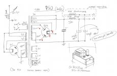
generally not suggested for this type of application. As I mentioned above, that it is a little bit different, i thought about EZ81 (6ca4). I draw 2 different cases and I think the second one is more suitable for you. see the attachment
note that for the first case choke=10H/200mA
regards
costas
PS sorry for the delay I was out of office yesterday
Attachments
Hi sarrisk
thanks alot for doing that. i got few questions,
can i dont use the 7824? as the application do not need to be regulated. or is it use to protect the tube rectifier?
i assume both application use the same tube right?
from duncan psud II, ISFM 1.8A and IFRM 0.5A. which one is the current rating?
sorry about these newbie questions. learning as much as i can.
for my application, i think the 1st setup will do the job. as i only need 150mA. how much voltage will be drop with that small current?
from psud II, EZ81 gives out the same DC voltage as the AC voltage in.
please correct me if im wrong. thx in adv
Its ok to use the first schematic. I think you are going to take about 20Volts output.
I dont know about duncan psud II - post the link to take a look.
For the second schematic 7824 is for the initial regulation and EZ81 is for extra regulation (no interference at all because of the valve). I thought about this because you are going to power your dac.
cheers
costas
P.S.
1. Yes both apps use the same tube
2.These are only schematics. I didn't test them to give you the exactly voltage and current.
hi sarrisk
Duncan's psu design at www.duncanamps.com/psud2/index.html
This program quite handy as it can simulate the output
What's the max current EZ81 can pass through? Some state 150mA. Some 250mA. Should I parallel the tube?
Duncan's psu design at www.duncanamps.com/psud2/index.html
This program quite handy as it can simulate the output
What's the max current EZ81 can pass through? Some state 150mA. Some 250mA. Should I parallel the tube?
milen007 said:k starting to get it.
I assume 5ar4 is to rectify high voltage which is why not suitable for 18v
PLs correct me if I'm wrong
Can someone suggest low voltage tube rec with higher current?
Tungar bulbs, but they are no longer made. High vacuum rectifiers are not designed for very low voltage operation at high currents.
- Status
- This old topic is closed. If you want to reopen this topic, contact a moderator using the "Report Post" button.
- Home
- Amplifiers
- Tubes / Valves
- learning tube rectified psu