I am not sure if you have given us sufficient information.
What is your B+, how do you have the screens strapped?
Are you intending bias for Class A, Class AB, Class AB2?
If I knew idle current or bias voltage, I could guess the
other from the 270R's. But I can't calculate what is your
intention from knowing just the cathode resistors.
What is your B+, how do you have the screens strapped?
Are you intending bias for Class A, Class AB, Class AB2?
If I knew idle current or bias voltage, I could guess the
other from the 270R's. But I can't calculate what is your
intention from knowing just the cathode resistors.
jkeny,
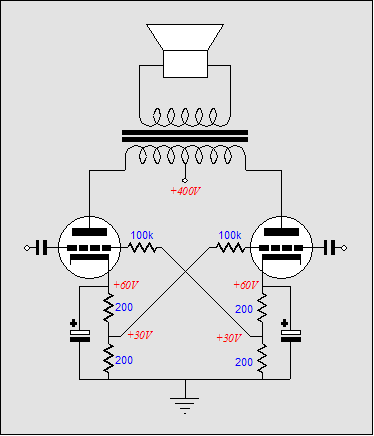
This scheme puts half the bias from the other push pull side onto the grid. Thus rather than (approximately) having the grid at 0V DC and the cathode at +14 DC you want +14 DC on the grid and +28V DC on the cathode. So BOTH cathode resistors need to be the same size as you are now using. So use 2 x 270R for each cathode.
The 100K shown need to follow the max Rg1 values for the tube - For ECL86 take those 100K up to 470K.
Cheers,
Ian
I may well try Shoog's variation on this biasing seen here: http://www.diyaudio.com/forums/attachment.php?s=&postid=1306043&stamp=1190309883
- Status
- This old topic is closed. If you want to reopen this topic, contact a moderator using the "Report Post" button.
- Home
- Amplifiers
- Tubes / Valves
- Blumlein's Garter Bias question