Has anyone ever tried to do the RJM passive phono with 12AY7 instead of the 6922? Mu is similar so it seems doable?
I have heard that the RCA circuit is not appropriate for AY7 due to lower mu (compared to AX7) but the topology is quite similar to RJM which uses a 40ish mu tube. As far as gain goes both RCA and RJM are two stage passive. So I would also be interested in hearing from anyone who has done the RCA phono with AY7s also.
I have heard that the RCA circuit is not appropriate for AY7 due to lower mu (compared to AX7) but the topology is quite similar to RJM which uses a 40ish mu tube. As far as gain goes both RCA and RJM are two stage passive. So I would also be interested in hearing from anyone who has done the RCA phono with AY7s also.
Hi, I'm not familiar with the RJM design you mention, but I have had good results using the 12AY7 as 2nd stage in RCA passive design, that 2nd socket has had all sorts of tubes tried, but I have kept going back to the 12AY7 in that slot, sufficient gain, and it seems to have a very even, uncoloured sound. In the first slot, I ran a 5755 for a long time, seemed to be free of what I heard as bass "mushiness" from a 12AX7, but changed back recently, just to find out if I was missing out on anything, not convinced yet.
mashaffer said:Has anyone ever tried to do the RJM passive phono with 12AY7 instead of the 6922? Mu is similar so it seems doable?
I have heard that the RCA circuit is not appropriate for AY7 due to lower mu (compared to AX7) but the topology is quite similar to RJM which uses a 40ish mu tube. As far as gain goes both RCA and RJM are two stage passive. So I would also be interested in hearing from anyone who has done the RCA phono with AY7s also.
Although the gain is similar, there is a large difference in plate resistance between the two tubes. I would think you would have to alter the values of the passive RIAA network if you used a 12AY7 to get the flattest response.
Hi guys.
Mike.
Right zout of first stage is part of r1, so just sutract that
amount from r1.
Alex. I belive you are right. If just changing second stage, I suppose you would just tweak the operating point to suit that tube. You said you used 6n1p's for yours? they have much less transconductance than 6dj8's. how do you like it so far?
Rolf.
rman said:
Alex. I belive you are right. If just changing second stage, I suppose you would just tweak the operating point to suit that tube. You said you used 6n1p's for yours? they have much less transconductance than 6dj8's. how do you like it so far?
Rolf.
I prefer the sound of the 6n1p over the Sylvania 6922 that I have. I also changed the operating point of the 6n1p, higher B+ (270VDC), 22K Plate load resistors, 330ohm cathode resistor, and I replace the coupling capacitor from 0.1uf to 0.22uf. I am still working on the new RIAA filter, but I found that lowering the 82k5 resistor a bit is close.
I find it hard to compute the RIAA, I can't find reliable data on the plate resistance of the 6n1p, Svetlana says 4.4K, some say it is as high as 7K. RJM computed the RIAA using 6dj8 which has a plate resistance of around 2K. I am recomputing the RIAA using 4.4K on the 6n1p and 22K plate resistor.
alexg said:
I find it hard to compute the RIAA, I can't find reliable data on the plate resistance of the 6n1p,
It is always best to measure it anyway.

Do you know the fundamental design rule for low noise amplifiers?
Try to find an answer in the question
link.
Sorry that I am not that well versed yet and I was not able to follow the relevance of the link. I could take a few guesses.
Keep resistances as low as reasonably possible, use low noise resistors, use low noise input tubes, don't use a pentode for the first stage, parallel multiple input tubes... did I stumble on it by chance?
Seriously though I have heard many good comments about this phono stage and would appreciate knowing what it is that you dislike about it.
alexg said:
I find it hard to compute the RIAA, I can't find reliable data on the plate resistance of the 6n1p, Svetlana says 4.4K, some say it is as high as 7K. RJM computed the RIAA using 6dj8 which has a plate resistance of around 2K. I am recomputing the RIAA using 4.4K on the 6n1p and 22K plate resistor.
4.4K plate resistance in parallel with your 22K resistor gives an R1 of 3.6K, and at http://www.kabusa.com/riaa.htm that yields R2=533ohms, C1=0.6uF and C2=0.2uF (to block the plate voltage from getting into the next tube's grid1, you could use a coupling cap and resistor for this grid circuit (which can be high impedance, which won't hardly much load the RIAA circuit) after this RIAA network.
I see your problem for getting a reliable value for the plate resistance, as the older datasheets imply a much different value. And as this value swamps the 22K plate resistor, getting this wrong will mess up the RIAA curve. At the cost of gain, you could insert some "artificial" resistance for R1 by adding a series resistor from the plate to the R2 C2 node. So if you assume the grand total for R1 will be 45K (add a 39K resistor in series) you'd get R2=6.5K, C1=0.047uF and C2=0.016uF and this would cut down the sensitivity of the accuracy of the RIAA curve to varying plate resistance of the tube.
You could use a trim-pot for adjusting R1, but that means you have to measure the response of the RIAA circuit, and that would be a PITA.
I see your problem for getting a reliable value for the plate resistance, as the older datasheets imply a much different value. And as this value swamps the 22K plate resistor, getting this wrong will mess up the RIAA curve. At the cost of gain, you could insert some "artificial" resistance for R1 by adding a series resistor from the plate to the R2 C2 node. So if you assume the grand total for R1 will be 45K (add a 39K resistor in series) you'd get R2=6.5K, C1=0.047uF and C2=0.016uF and this would cut down the sensitivity of the accuracy of the RIAA curve to varying plate resistance of the tube.
This is kind of what I was thinking. As long as we are using a tube with an rp substantially less than the series resistance the circuit should be relatively immune to tube changes. Of course we could complicate it further by using a choke for the plate load.

@ mashaffer
Hello mashaffer
Yes, in your circuit you have to keep the resistances as low as reasonably possible,
use low noise resistors, use low noise tubes at the input and
 the second stage must be low noise too.
This is because the topology has a fundamental mistake.
Maybe the attachment in this post
helps you understanding what's wrong.
You will see that lots of phono stages are suffering with these problems.
I think it must be a mixture of ignorance, commercial interest and low technical knowledge
why the "audiofools" still do it this way.
Hello mashaffer
Originally #12 posted by mashaffer
Sorry that I am not that well versed yet and I was not able to follow the relevance of the link. I could take a few guesses.
Keep resistances as low as reasonably possible, use low noise resistors, use low noise input tubes, don't use a pentode for the first stage, parallel multiple input tubes... did I stumble on it by chance?
Seriously though I have heard many good comments about this phono stage and would appreciate knowing what it is that you dislike about it.
Yes, in your circuit you have to keep the resistances as low as reasonably possible,
use low noise resistors, use low noise tubes at the input and
the second stage must be low noise too.This is because the topology has a fundamental mistake.
Maybe the attachment in this post
helps you understanding what's wrong.
You will see that lots of phono stages are suffering with these problems.
I think it must be a mixture of ignorance, commercial interest and low technical knowledge
why the "audiofools" still do it this way.
Sorry, I am still not following you. The only attenuation is the unavoidable attenuation of the filter network at the output of the first stage.
One could use an active load such as cascode or mu stage to increase the gain of the first stage which would, in theory, reduce the proportion of noise presented to the second stage. Is this the approach that you are thinking of or am I off course here?
Of course then we have to be sure that no negative effects result. Questions such as does the extra active device add its own noise?; Does the more complex circuitry constrict dynamics and openness? come to mind right off the bat.
I am not suggesting what the answers to such questions might be as I have no idea. I am sure this has been addressed somewhere.
It seems worth while for me to build a basic circuit first and then try the fancier approaches and see for myself. It won't happen very quickly because of other irons I have in the fire (and limited resources) but it seems the best way to learn.
@ mashaffer #16
Hello Mike,
Yes, you are on the right way.
In a well done design, the noise of the input stage is
relevant for the signal to noise ratio of the whole preamp.
You must ensure that the gain of the input stage is
more than the damping of the filter.
In your case the signal damping of the RIAA network is up to
40dB but the gain of your triode is less.
This is a fundamental mistake because the noise of the RIAA components
and the noise of the second stage becomes relevant now.
You will see that lots of passive RIAA pres suffer with this problem.
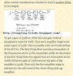
The attenuation is not unavoidable,
because the RIAA eq. can be done in two steps.
This makes it possible to use the passive triode topology you want.
See attachment, passive RIAA in two stages.
See fig 4.4.1 and Ronald's design
http://Maarten@platenspeler.com/background/riaa/uk_riaa_background_4.html
Kind regards,
Darius
http://coupling-triode.blogspot.com/
Originally #16 posted by mashaffer
Sorry, I am still not following you. The only attenuation is the unavoidable attenuation of the filter network at the output of the first stage.
One could ... increase the gain of the first stage which would, in theory, reduce the proportion of noise presented to the second stage. Is this the approach that you are thinking of or am I off course here?
...
Hello Mike,
Yes, you are on the right way.
In a well done design, the noise of the input stage is
relevant for the signal to noise ratio of the whole preamp.
You must ensure that the gain of the input stage is
more than the damping of the filter.
In your case the signal damping of the RIAA network is up to
40dB but the gain of your triode is less.
This is a fundamental mistake because the noise of the RIAA components
and the noise of the second stage becomes relevant now.
You will see that lots of passive RIAA pres suffer with this problem.
The attenuation is not unavoidable,
because the RIAA eq. can be done in two steps.
This makes it possible to use the passive triode topology you want.
See attachment, passive RIAA in two stages.
See fig 4.4.1 and Ronald's design
http://Maarten@platenspeler.com/background/riaa/uk_riaa_background_4.html
Kind regards,
Darius
http://coupling-triode.blogspot.com/
Attachments
mashaffer said:Ahh... I had seen that approach I just forgot about it. Thanks.
Maybe you are able to explain this to John B. .
Oh, I would never presume to teach JB anything. He has forgotten much more about tubes than I have ever even known.
One of the interesting things about electronics is that there is always another way to do things that can improve some aspect of performance or sound quality. It gives spice and interest to life.
I appreciate you staying with me while we sorted this out.
One of the interesting things about electronics is that there is always another way to do things that can improve some aspect of performance or sound quality. It gives spice and interest to life.
I appreciate you staying with me while we sorted this out.
- Home
- Amplifiers
- Tubes / Valves
- RJM with 12AY7