Hi there
Is auto-bias just another fancy name for fixed bias?
How easily can a "manual bias" system be converted to auto bias?
I am busy remodding a tube amp and to keep with a clean look thought why not convert it to auto-bias.
It is an SE design using a single 6C33C tube.
D
Is auto-bias just another fancy name for fixed bias?
How easily can a "manual bias" system be converted to auto bias?
I am busy remodding a tube amp and to keep with a clean look thought why not convert it to auto-bias.
It is an SE design using a single 6C33C tube.
D
GlidingDutchman said:
Is auto-bias just another fancy name for fixed bias?
No. Highly recommended that you do read some book on tube circuits.
Auto bias simply means cathode bias. Conversion may be easy but depends upon power supply as you need the extra volts that the cathode resistor will drop. Some other parameters change too.
Why do you want to convert?
Why? For sake of ease of use and sleek looks.
I am an old QUAD mkII user and never had to "bias" - it is a new thing for me as I got the SE am as a gift from a friend.
Probably then have to install a small ammeter on the chassis with a selector knob to make it more convinient.
Any suggestions?
D
I am an old QUAD mkII user and never had to "bias" - it is a new thing for me as I got the SE am as a gift from a friend.
Probably then have to install a small ammeter on the chassis with a selector knob to make it more convinient.
Any suggestions?
D
Suggestions? Yes, show a circuit. Is this a diy amp?
The conversion will certainly change the sonics among other things. Are you really looking forward to a cathode cap?
What's wrong with the ammeter? There is also the option to use a window comparator with led indication or even go for a full blown, micro-adjusted automatic bias.
The conversion will certainly change the sonics among other things. Are you really looking forward to a cathode cap?
What's wrong with the ammeter? There is also the option to use a window comparator with led indication or even go for a full blown, micro-adjusted automatic bias.
The circuit is not incomplete and does work.
It is a prototype amplifier developed by Alan Hobkirk from ISIS Audio in Capetown.
D
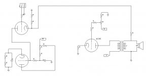
See attached image of amp section - the part of the circuit diagram I attached.
I have also mapped the PSU sections. Four in total.
Heaters
High Tension for output
Bias
and driver section
It is a prototype amplifier developed by Alan Hobkirk from ISIS Audio in Capetown.
D
See attached image of amp section - the part of the circuit diagram I attached.
I have also mapped the PSU sections. Four in total.
Heaters
High Tension for output
Bias
and driver section
Attachments
GlidingDutchman said:The circuit is not incomplete and does work.
Whatever you say chief
")
analog_sa said:
Whatever you say chief
Am I missing something? Yesterday when the amp arrived I turned it on and had a listen - it works and have good gain.
...
D
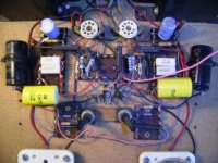
analog_sa said:I have made no references to the amp, only to the circuit. Apart from the fact that it looks drawn by a child (hopefully not by Alan Hobkirk) it misses at least one vital connection to the grid of the 6C33 - presumably the fat yellow caps on your picture.
Oeps - now I feel like a poephol! My mistake.
Just now compared my hand-drawn circuit and the PC one and saw I missed a vital connection... ai, ek van ook somtyds stront aan. Jammer vir daai een.
Yes - the big yellow cap...
D
PS - Drawn by a child?? Huh? How else must the thing be drawn? By Picasso? Pointers please?
Attachments
GlidingDutchman said:
PS - Drawn by a child?? Huh? How else must the thing be drawn? By Picasso? Pointers please?
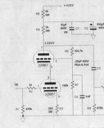
A Picasso interpretation of standard tube circuits? Could be.
May i suggest a slightly more conformist approach?
Attachments
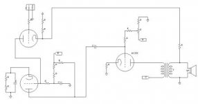
And now let's answer the original question:
This circuit uses a combination of fixed bias and autobias. Fixed bias is a variable negative voltage (relative to the cathode) applied to the grid. Autobias is a positive voltage drop (relative to the grid) on the cathode resistor (bypassed or not), caused by the idle current. The latter is kinda self-stabilizing.
This circuit uses a combination of fixed bias and autobias. Fixed bias is a variable negative voltage (relative to the cathode) applied to the grid. Autobias is a positive voltage drop (relative to the grid) on the cathode resistor (bypassed or not), caused by the idle current. The latter is kinda self-stabilizing.
SY said:Drawing style. As is, it can be puzzled out with a great deal of effort (it turns out to be utterly conventional), but it's just as easy to draw the circuit so that the people whom you want to help you are more likely to help you.
Okay -
I left out the component values as this is not my design but a design from a registered company. This is however a prototype that never were produced...
I am currently chatting with the designer.
Cheers
D
oshifis said:This circuit uses a combination of fixed bias and autobias.
I won't be certain without resistor values. That Rk maybe just a 1ohm fuse or a convenient point to measure the bias. To some extent it is combo bias anyway.
- Status
- This old topic is closed. If you want to reopen this topic, contact a moderator using the "Report Post" button.
- Home
- Amplifiers
- Tubes / Valves
- Auto-bias - easy to convert to or not?