thanks for the input
i am planing to use this with a stanton mm 680 or something simular .......
i am a transistor guy but as since i have so many of these tubes i thought about building something with them .....
your opinion about the rest of the circuit will be very usefull ......
also some information about the all thing since i have no idea how all this is working .....
i presume that the first tube is working as a buffer then the second makes the riaa equalization ...and then the third ????what is it for ????
thanks
Sakis,
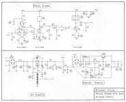
That design uses 3 cascaded common cathode gain stages. It appears that the RIAA EQ circuitry is split. The R5/C5 combination is a low pass filter.
I'd be very cautious about using that design to drive a low I/P impedance line stage. Adding an IRFBC20 source follower DC coupled to the 6J5's plate will resolve that issue.
UF4007 diodes are a drop in replacement for 1N4007s that generate less switching noise. The same noise consideration suggests Schottky diodes be used in the heater PSU bridge.
FWIW, I too would not use that circuit with a LOMC. S/N performance is likely to be unacceptably poor.
i presume that the first tube is working as a buffer then the second makes the riaa equalization ...and then the third ????what is it for ????
The RIAA is in two parts. A filter before, and after the middle tube.
I am wondering at the advantages of paralleled input tubes, and also why all the paralleled load resistors.
The 3rd tube looks like an attempt to provide a low impedance drive with using cathode follower. Some people don't like to use cathode followers - say they sound bad. Not sure I agree.
hotbottle said:
The RIAA is in two parts. A filter before, and after the middle tube.
I am wondering at the advantages of paralleled input tubes, and also why all the paralleled load resistors.
The 3rd tube looks like an attempt to provide a low impedance drive with using cathode follower. Some people don't like to use cathode followers - say they sound bad. Not sure I agree.
Look at the schematic carefully, the O/P is taken from the anode of the 3rd stage. All 3 stages are configured common cathode.
I suspect the reasons for paralleling load resistors are obtaining a specific value and increased power handling capability.
Using parallel sections in the I/P stage doubles gm, which can contribute to an improved S/N ratio.
Look at the schematic carefully, the O/P is taken from the anode of the 3rd stage. All 3 stages are configured common cathode.
Oops, I really meant to say withOUT, not with.
Can't believe I mistyped that... sorry

The power supply....
First ....The purpose of D1 is to protect the body diode from blowing durring shut-down.... Watch that the forward voltage drop of D1 is lower than the body diode at Worst Case Analysis over temp....
I don't see the advantage of R10...It actually hinders the supply perfromance....an L would be better there, but still not needed..
Also..the zener string needs to be feed from a PNP CCS..for better audio and noise rejection from the BUS.... essentially making the regulated supply lower in noise, which is critical in phono stages...
I would also use a higher voltage ratted part than the IRF530...
Be carefull durring start-up condition...The GATE is at 0 volts at time 0...... The voltage at the Drain may rise faster the RC at the GATE...you can put a zener across R16 to protect the FET for that few seconds the Drain to Gate voltage "may" be excessive....
Chris
My comment on the power supply is that it is way over-complicated. Maybe I am going against common wisdom here, as I haven't been posting here long, but I am in favour of keeping things simple. I don't, as a rule, use regulated power supplies, especially not for heaters. If people disagree, well at least it'll make for an interesting discussion ")
I run my phono stage heaters from DC, but it's a simple filtered supply. I arrange to drop enough voltage by resistance, so that the heaters end up with correct voltage on them. Why should it ever vary enough to matter?
I run my phono stage heaters from DC, but it's a simple filtered supply. I arrange to drop enough voltage by resistance, so that the heaters end up with correct voltage on them. Why should it ever vary enough to matter?
i had my thought
about power supply also .....
but this is secondary the most importand is the phono stage ...i was actually thinking about building something even more simple but yet my theory on tubes is not really enough ....
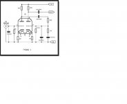
i ve seen a phono stage that works with ecc83 and i was curious if possible to convert the circuit to make operate with 12ay7.....
here is the circuit
about power supply also .....
but this is secondary the most importand is the phono stage ...i was actually thinking about building something even more simple but yet my theory on tubes is not really enough ....
i ve seen a phono stage that works with ecc83 and i was curious if possible to convert the circuit to make operate with 12ay7.....
here is the circuit
Attachments
i ve seen a phono stage that works with ecc83 and i was curious if possible to convert the circuit to make operate with 12ay7.....
Sakis,
In addition to recalculating the RIAA network values, you have a MUCH bigger problem in making a 'Y7 for 'X7 swap. The net gain of the circuit is INSUFFICIENT.
The net gain of the "classic" RCA circuit is 45 dB. Which is just about right for bringing 5 mV. up to line level. The amplification factor (mu) of the 'X7 triode is 100, while the mu of the 'Y7 triode is 40. A RCA style circuit using 'Y7 sections will not pass muster.
hotbottle said:My comment on the power supply is that it is way over-complicated. Maybe I am going against common wisdom here, as I haven't been posting here long, but I am in favour of keeping things simple. I don't, as a rule, use regulated power supplies, especially not for heaters. If people disagree, well at least it'll make for an interesting discussion
I run my phono stage heaters from DC, but it's a simple filtered supply. I arrange to drop enough voltage by resistance, so that the heaters end up with correct voltage on them. Why should it ever vary enough to matter?
Hotbottle,
I agree that the heater PSU shown is overly complicated. However I disagree about using regulation. "Full wave" voltage double 6.3 VAC using a pair of Schottky diodes into a pair of high capacitance 'lytics. Follow the doubler stack with a 7812 3 terminal regulator. Next!

Eli/Jeff,
My first play with DC heaters was almost exactly like you describe. However, I could not convince myself that a tube running from regulated DC would sound any different, or would last any longer etc, than one running from plain filtered DC.
The only negative thing I thought was that there would be a small residual ripple on the DC, and given that, in a well built/designed preamp run from ac heaters, you can keep the hum pretty low anyway, I didn't think a small percentage of ripple was going to be audible.
There was one other small thing against a regulator - I wanted to minimise the silicon in my amp.
- Status
- This old topic is closed. If you want to reopen this topic, contact a moderator using the "Report Post" button.
- Home
- Amplifiers
- Tubes / Valves
- phono stage