G'Day,
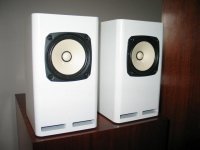
Next project is a point-to-point ECL82 push-pull. Previous projects were a Tubelab SimpleSE and a point-to-point 6P15P SE. This project is intended to be a learning process, I will be using it to power some Fostex FE127E speakers in 4.5 litre cabinets in my office with the source being my Mac. I want to learn techniques for building an amp and gain some experience before embarking on a more complex EL84 PP "Baby Huey" designed by GingerTube for my main system. First ECL82 effort was unsuccessful, a little too ambitious as a first point-to-point build. Subsequent 6P15P I paid particular attention to grounding and managed to get a hum-free result straight up.
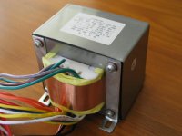
Now my question. I have chosen this project http://www.bonavolta.ch/hobby/en/audio/ecl82_3.htm There are a couple of issues. First, I managed to pick up a cheap power transformer while in Singapore a few weeks ago. Trouble is, it only has 2A + 2A 6.3V. That is sufficient to run the 4 ECL82s, but not enough current to run the EZ81 rectifier. It has a 3A 5.0V tap, so I am going to run a GZ34 or 5U4G rectifier. From what I can gather, the specified 100uF first filter cap will be too large. I have a 50+50uF JJ multi section cap that I can use. Can I use the 50+50 in place of the two 100uF caps, or will this be insufficient filtering? Next point is that as this is a "learner project" and funds and real estate in the chassis are limited, I have decided to omit the 8-10H choke. Can I simply substitute a resistor of about 150R in its place? Next question, in the power supply schematic, there appears to be three 470K 3W bleeder resistors. Are all of these necessary? I have the book that this schematic comes from, and there is no mention of design goals with the power supply.
Picture of the cheap power transformer attached...
Any help or advice is greatly appreciated!
Thanks,
Chris
Next project is a point-to-point ECL82 push-pull. Previous projects were a Tubelab SimpleSE and a point-to-point 6P15P SE. This project is intended to be a learning process, I will be using it to power some Fostex FE127E speakers in 4.5 litre cabinets in my office with the source being my Mac. I want to learn techniques for building an amp and gain some experience before embarking on a more complex EL84 PP "Baby Huey" designed by GingerTube for my main system. First ECL82 effort was unsuccessful, a little too ambitious as a first point-to-point build. Subsequent 6P15P I paid particular attention to grounding and managed to get a hum-free result straight up.
Now my question. I have chosen this project http://www.bonavolta.ch/hobby/en/audio/ecl82_3.htm There are a couple of issues. First, I managed to pick up a cheap power transformer while in Singapore a few weeks ago. Trouble is, it only has 2A + 2A 6.3V. That is sufficient to run the 4 ECL82s, but not enough current to run the EZ81 rectifier. It has a 3A 5.0V tap, so I am going to run a GZ34 or 5U4G rectifier. From what I can gather, the specified 100uF first filter cap will be too large. I have a 50+50uF JJ multi section cap that I can use. Can I use the 50+50 in place of the two 100uF caps, or will this be insufficient filtering? Next point is that as this is a "learner project" and funds and real estate in the chassis are limited, I have decided to omit the 8-10H choke. Can I simply substitute a resistor of about 150R in its place? Next question, in the power supply schematic, there appears to be three 470K 3W bleeder resistors. Are all of these necessary? I have the book that this schematic comes from, and there is no mention of design goals with the power supply.
Picture of the cheap power transformer attached...
Any help or advice is greatly appreciated!
Thanks,
Chris
Attachments
Chris,
Look at the 6CA4/EZ81 data sheet. 50 muF. is the limit for the I/P cap. So, you know the designer of that circuit doesn't respect published limits.
Using a 5AR4/GZ34 is a good plan. A single section of your 2X 50 muF. cap. in the 1st position is within published limits. Parallel the 2nd 50 muF. section with a 100 muF. part. The total capacitance is the same, but it's distributed in manner that respects published limits.
IMO, the 1 MegOhm value shown for R1 (the I/P grid leak part) is a selection of dubious merit. High freq. roll off could easily occur. 100 KOhms is, in my thinking, a better choice.
FWIW, I have reservations about the phase splitter circuitry too. For very good reasons, LTPs and "concertina" splitters are "in vogue". That circuit uses neither of the preferred topologies. It appears to be paraphase.
What is going to drive your 6BM8/ECL82 project?
Thanks for taking the time to respond Eli,
This project is just a "learner". Using output transformers (cheap 10 watt Edcor PP open frame) salvaged from my first ECL82 project http://www.bonavolta.ch/hobby/en/audio/ecl82_2.htm This project did not work, but I do not consider it a failure. It hummed and buzzed like crazy, but did amplify the signal... I tried to get too much into too small a chassis for my first point to point project. Learned a lot about grounding on the way, my next effort was a lot better due to the lessons learned.
That original ECL82 project (Mullard) looked a little complex, one extra tube than the Rainer zer Linde design I listed in the first post. I have no attachment to the design and am happy to abandon it in favour of a better option. My aim is to keep things simple, trying to keep it to just the four ECL82 tubes if possible. A question about the Mullard design ( http://www.bonavolta.ch/hobby/en/audio/ecl82_2.htm ), the first tube introduces a lot of gain, was this originally designed as a phono pre-amp stage? If so, maybe I could modify this design slightly by removing the first stage.
To answer your question Eli, this amp will be sourced from the headphone jack of my macbook pro, playing iTunes. Absolute hi-fi not required, using this project to gain building skill before attempting a more complex EL84 project with constant current source etc.
Have seen your "el cheapo" design and was thinking maybe of adapting it, but was hoping for something a little simpler to concentrate on issues such as layout and alowing simpler fault finding if required.
If it is some help recommending options, here are the parts I have available:
Power transformer: 280-230-0-230-280v 150mA, 5V 3A, 6.3V 2A, 6.3V 2A, 12.6V 1.5A
Output transformers: Edcor XPP 10-8-8K (10 Watt, 8K:8 ohm Push Pull)
Rectifiers: GZ34, 5U3C (Svetlana 5U4G), EZ81
Caps: JJ 50uF+50uF, JJ 100uF+100uF, 80uF PIO Motor Run, several ASC 20uF+4uF motor run caps
plenty of Russian 0.22uF PIO 500 V coupling caps
some solen 0.47Uf coupling caps
Thanks for the help,
Chris
Have done a little more searching. Does this look like a better schematic? http://www.geocities.com/asl_wave8/schem/wave8stock.pdf
Thanks again,
Chris
Thanks again,
Chris
My 1st thot would be to just use the 4 6BM8s to do a simplified El Cheapo... a primary simplification could be the replacement of the CCS for just a big resistor to a negative supply . Something like what Poinz did on the front of this...
http://www.audiotropic.net/Projects/machine1.html

Eli might have some ideas too.
dave
http://www.audiotropic.net/Projects/machine1.html
Eli might have some ideas too.
dave
Thanks for the response Dave.
Still very much a beginner with all of this, hence the idea of a simple build. For the negative supply, can I simply tap off one of the unused high voltage secondary windings? For example, with my 280-230-0-230-280 transformer, if I use the two 280 volt taps for the B+, can I use one of the 230 volt taps through a diode to provide the negative supply?
And for info, the amp will be powering these speakers. Look familiar?
Cheers,
Chris
Attachments
Be careful of overloading the input triode. Most designs will only bias it up at less than -1V. Also The gain on the triode is about 60x with a perfect load - what are you going to do with all that gain ? Think of a voltage divider on the input such that the grid will never see more than 0.5V. Even better a step down transformer will sound a lot better.
The ECl82 is a tricky candidate to deal with.
Shoog
The ECl82 is a tricky candidate to deal with.
Shoog
chrish said:Have done a little more searching. Does this look like a better schematic? http://www.geocities.com/asl_wave8/schem/wave8stock.pdf
Thanks again,
Chris
Is the Pope Catholic? Do bears sh*t in the woods? You bet that design is better. The "Wave" small signal circuitry is common cathode gain DC coupled to a "concertina" phase splitter. Excellent!
Copy the 56 nF. cap. at the I/P from "El Cheapo". You protect the O/P trafo cores against saturation.
Thanks again Guys for your time and your patience.
I suspect that perhaps I have fallen for the trap of asking "I have these great wheels, what car should I build" type situation. Yes I have the 6BM8/ECL82 tubes, but I also have some extra:
ECC81/12AT7
6N2P (similar to 12AX7/ECC83)
6N1P (similar to ECC88)
6P15P (similar to EL83)
6P3C (Similar to 6L6GT)
Have I been limiting myself by only considering an ECL82 build? Limitations are space in the chassis, build will be in the same chassis as for this 6P15P SE build http://www.diyaudio.com/forums/showthread.php?s=&threadid=113917 small output transformers (10 watt 8K) and the power transformer as listed above.
Eli, I assume that you mean to put a 56 nF capacitor after the RCA input, before the 100k input grid leak resistor (this will be a straight power amp, no volume control)? I am also guessing that as this forms a HP filter at about 28 Hz, it is the low frequencies that you are trying to keep out that will saturate the core of the small output transformers?
Thanks for your patience,
Chris
Have I been limiting myself by only considering an ECL82 build? Limitations are space in the chassis, build will be in the same chassis as for this 6P15P SE build http://www.diyaudio.com/forums/show...threadid=113917 small output transformers (10 watt 8K) and the power transformer as listed above.
Eli, I assume that you mean to put a 56 nF capacitor after the RCA input, before the 100k input grid leak resistor (this will be a straight power amp, no volume control)? I am also guessing that as this forms a HP filter at about 28 Hz, it is the low frequencies that you are trying to keep out that will saturate the core of the small output transformers?
Chris,
Having set yourself up to use the 6BM8, follow through on the plan. Shoog's remarks about the type being difficult to make sound good could easily be related to SE topology. The ASL Wave 8 you will "clone" enjoyed its share of respect. Compare the 6BM8's triode with a 12AT7. While not identical, there is a strong resemblance. With a HD distortion spectrum skewed towards 2nd order, the 'T7 is bad sounding in SE circuitry. OTOH, the 'T7 is terrific in PP circuitry, as it combines WELL with the cancellation of even order HD products found in the "finals".
Yes, the 56 nF. caps. replace the wires between the I/P RCA jacks "hot" connections and the tubes. Budget O/P trafos have mediocre performance in the deep bass region. As a consequence, a large NFB error correction signal is generated. The result is nasty sounding core saturation. Stopping the trouble, with a high pass filter at the I/P, before it can occur is (IMO) obvious. Keep in mind that the lowest note on a double bass is above the selected 3 dB. down point.
")
Thanks again everyone for taking the time and effort to offer your help and advice.
If I might just ask one more question reference the "Wave" design. Looking at the Mullard design, the first ECC83 is biased at 1.5 volts, then the following triode stages of the ECL82s are biased at 2 volts. With the Wave design, the bias of the input tube is 0.7 volts. Will this, as Shoog suggested, lead to early clipping of the input signal? Should I not worry about it, or as suggested, use some form of voltage divider to prevent overdriving the input. Maybe a volume control such as a multi-turn trimmer pot that I can set under the chassis in place of the 100k fixed input grid resistor.
Thanks again guys, really appreciate the input.
Chris
Running the ECl82 triodes at -2V bias will mean them passing tiny currents, which to my mind is not such a good idea. Stray currents might easily get sucked into the signal and cause hum.
I would definately consider some sort of voltage divider on the Wave design. If I were you I wouldn't want the input signal coming any higher than 0.5V. You might find that using one of your other valves to do the voltage amplification would be worthwhile. The ECC88 makes a good voltage amplifier.
I used microphone transformers at the input of my headphone amp. They stepped down the signal by 9:1+1 and drove the triodes in a grid leak biased LTP. I can post the schematic when i get home if you think it might inspire you.
Shoog
Thanks for the input Shoog.
Reading the above posts has got me plotting the load lines of the design and looking up how a concertina phase splitter works trying to work out what the design criteria were for the amp. I am a bit slow picking up this valve amp stuff, but with the patient help of you guys, I have learned quite a bit.
This amp has always been just to learn techniques, and to provide a reasonable amp that will suit the mid-fi requirements of the computer MP3 source and the small bookshelf speakers. The trouble I had with my first point-to-point push pull build was that I got too ambitious with complexity and tried to put it all in a too small chassis. Hence I want to keep things simple. Adding an extra tube (or re design with better driver/power tube combo) might be the best solution for a competent builder, but I think I need it simple to so that I can build my experience and confidence. To that end, I think I might finalise on the "Wave" design. Regarding the recommended voltage divider, would simply making the input 100k resistor a 100k trimpot do the job? I have a simple signal generator and scope, so could set the trimpot to a suitable level and then forget.
Also, university studies begin again soon (in addition to my full time work), so don't want to get too distracted with head in the books designing an amp from first principles just yet. This has to be a gentle journey for me
Given the requirements and available parts, is this looking like a good choice?
Once again, thanks for the patience with my many questions,
Chris
Shoog said:I used microphone transformers at the input of my headphone amp. They stepped down the signal by 9:1+1 and drove the triodes in a grid leak biased LTP. I can post the schematic when i get home if you think it might inspire you.
From your earlier post, the idea of using a step-down transformer between the triodes in LTP, and the outputs in pentode has me wondering what that would look like in more detail.
dave
Regarding the recommended voltage divider, would simply making the input 100k resistor a 100k trimpot do the job? I have a simple signal generator and scope, so could set the trimpot to a suitable level and then forget.
Chris,
The high pass filter at the I/P requires tight tolerance in the resistance. You will not get that in a low cost trim potentiometer. Therefore, a fixed voltage divider made from 1% tolerance metal parts is in order.
The "Wave" circuit biases the I/P grid at -0.7 VDC, which means an AC signal of 0.5 VRMS clips. The standard for CDPs is a peak O/P of 2 VRMS. The volume control in the source equipment attenuates the signal, but you don't want to get caught in a "hair trigger" situation. Dropping 2/3 of the I/P voltage in the divider should leave you well placed. Wire 1% tolerance 69.8 KOhm and 30.1 KOhm metal film resistors in series. The "free" end of the 69.8 K part connects to the high pass cap., while the "free" end of the 30.1 K part is grounded. The junction of the 2 resistors is the point the grid drive signal is taken from.
Thanks for the explanation Eli. Makes me wonder why the designers of this circuit did not consider something like this when they designed it.
Studying for one of my ongoing licence examinations (4 per year, YUK!) then away for a week, so should be able to start the build in about 2 weeks. Will keep you posted on the progress.
Cheers, and thanks again,
Chris
Studying for one of my ongoing licence examinations (4 per year, YUK!) then away for a week, so should be able to start the build in about 2 weeks. Will keep you posted on the progress.
Cheers, and thanks again,
Chris
Chris,
If I were you I would convert the Wave circuit to a LTP front end. This reduces the overall gain to a managable level and efficiently uses the two triodes. The split load phase splitter has zero gain and that is why you need the input triode to introduce gain before the phase splitter.
I highly recommend trying something like my headphone amp circuit. The front end can be converted to cathode bias and the input transformer can be replaced with the voltage divider discussed. The LTP can have a more conventional anode resistive loading. Your feedback can be applied to the undriven LTP triode. My circuit uses a more noval form of freedback which to my mind sounds superior to gNFB.
It then becomes a two stage amplifier rather than a three stage.
Shoog
- Status
- This old topic is closed. If you want to reopen this topic, contact a moderator using the "Report Post" button.
- Home
- Amplifiers
- Tubes / Valves
- ECL82 power supply question