Years ago, Glass Audio ran an article that mentioned a series of complex cathode followers called augmented cathode followers. Kind of an instrumentation amplifier, perhaps, very high performance in certain parameters.
They were pretty interesting but relatively more complicated - maybe 3-4 tubes at least two power supplies etc, but impressive performance on paper.
Has anyone here ever built/listened to one for audio?
Thanks
Murray
They were pretty interesting but relatively more complicated - maybe 3-4 tubes at least two power supplies etc, but impressive performance on paper.
Has anyone here ever built/listened to one for audio?
Thanks
Murray
Yes, I've played with them. I think that with a properly designed cathode follower, these are generally not necessary. Other may (and do, notably Allen Wright) disagree. The idea is to fix the cathode-plate voltage so that the grid capacitance isn't modulated.
A properly designed and appropriately used cathode follower will give an impressive performance on the test bench. And listening backs that up, at least in my living room.
A properly designed and appropriately used cathode follower will give an impressive performance on the test bench. And listening backs that up, at least in my living room.
I have a ccs loaded 6922 cathode follower in front of my gainclone .
It certainly doesn't degrade the signal in any way compared to a signal fed directly to the gainclone. On the other hand it improves the interface to the source and some sounds are even better than a direct connection.
I can't imagine how it could be improved upon audibly by making it more complex. However it could possibly make an improvement on measurements.
Years ago, Glass Audio ran an article that mentioned a series of complex cathode followers called augmented cathode followers.
Does anyone know what issue this article was in? I have been through my stack of old Glass Audio magazines and can't find it. I don't have every issue though. I would like to read this article.
I have been experimenting with using cathode followers as output stages. Fixing the plate to cathode voltage seems to remove most of the distortion components created in the tube. I believe that it has to do with removing the voltage related parameter shifts inherent in the tubes, but I am still experimenting.
I have built some pretty complex cathode follower designs including one using DSP and SMPS technology. It recently won a prize in a Circuit Cellar design contest, not bad for a tube amp in a high tech embedded systems magazine!
Why would you want to do this? How about 20+ watts at 1% distortion from a single ended triode in class A with a plate efficiency near 50 %. The signal path is all tube. I am still tweaking the design, but it will be on my web site early next year.
TubeLab - if I find either the GA mag or the photocopy of the Journal referenced I'll post it. I honestly cannot find 75% of what I look for on any given day due to the accumulation of priceless krap that has just been doubly densified (another made up verb?) to give up half the basement for a family room.
I am on a quest to procure walking room, and by unloading some things I'll be able to dig down to another layer of a previous civilization. I know what color the envelope is (manila!) and the postmark/sender's address. I just have to find the box it's in.
Other Questioner, regarding advantages of the ACF variations, I think I recall 6-7 figure bandwidth, much much lower output impedance (I don't know if it got into op amp territory), and distortion on the order of 20 ppm (apparently conserving zeroes...on the fly, is that 0.002%?)
Happy Holidays all,
Murray
multi-volti:
Don't panic looking for anything. I got the IEEE journal publication from Jose. The described technique of the ACF-2 circuit is somewhat similar to what I am doing. I have built a circuit with 6336's driving a 600 ohm OPT. In one itteration I am using stacked triodes like Macdonald shows. In another I replace the top tube (V4) with a mosfet, and in yet another version I replace V4 with a DSP controlled agile SMPS. This allows V3 to operate with a constant 50 to 100 volts across it, and the SMPS (replacing V4) dissipates very little power. The total efficiency is in the 50% range (20 watts dissipated for 20 watts output), and distortion is under 1%. It just has this pesky problem of blowing up occasionally, nothing serious.
I am still in the experimenting stages, but I have built, measured, and listened to some unique amplifiers that exhibited some very impressive measurements for SE tube gear and sounded good too. I plan to post it all in the coming months on my web site.
I thought that I had found something new, but it has been said that all of the possible vacuum tube circuits have been invented already. Maybe this is true, but all of the possible embodiements and applications have not been developed yet.
I too have magazines, papers, and even circuits that I built dating back to the late 1960's. Finding things has become more and more difficult as the years and the "stuff" pile up. I know that I have some more Glass Audio issues in another box somewhere, I just don't have the time to dig for them right now.
What do you organized people DO with all your spare time
We only have the appearance of organization.
I DID find my 5867's, or was it 5687 (I have both, but can tell them apart :O)
Isn't one of those a big RF triode similar to a 3-500Z? I have some of them around here somewhere, but no suitable OPT's.
multi-volti said:What do you organized people DO with all your spare time?
You should see my office, my workbench, and my 3-car garage...
-- josé k.
I've been reading thru the copy Jose sent. These look like what we would call unity gain buffers these days. I'm sure some similar versions have shown up on the TubeCad journal, maybe the tube Buffers article.
I seem to recall that Ross MacDonald wrote some articles on pre-distortion too. Think I saw them listed in the RDH4. I'll bet the two amplifier references (1 & 2) on the last page of the Augmented CF paper are interesting designs.
Don
I seem to recall that Ross MacDonald wrote some articles on pre-distortion too. Think I saw them listed in the RDH4. I'll bet the two amplifier references (1 & 2) on the last page of the Augmented CF paper are interesting designs.
Don
I just looked on Ross Macdonald's web site! (Wonder if he is still around! He has journal papers published in 2007!)
"Active-Error Feedback and its Application to a Specific Driver Circuit," Proc. I.R.E. 43, 808-813, July (1955). Theoretical and experimental. See also: Instruments and Automation 28, 1938, November (1955). Also: Letter-to-the-editor, Wireless World 79, 295, June (1973).
"A Multi-Loop, Self-Balancing Power Amplifier," I.R.E. Trans. on Audio AU-3, 92-107, July-August (1955). Experimental. See also Instruments and Automation 29, 288, February (1956). I.R.E. P.G.A. Senior Paper Award, 1957.
"Nonlinear Distortion Reduction by Complementary Distortion," I.R.E. Trans. on Audio AU-7, 128-133, September-October (1959). Theoretical.
"Reply to Comments on 'Nonlinear Distortion Reduction by Complementary Distortion'," I.R.E. Trans. on Audio AU-8, 104-105, May-June (1960).
"More on Nonlinear Distortion Correction," I.R.E. Trans. on Audio AU-9, 103-105 July-August (196l). See also: dB, 13, 2,4, November (1979); 14, 6,8, April (1980); and 14, 6,7, December (1980).
ashok said:Can I have a copy of the paper"Some augmented cathode follower circuits" please ?
...
amadhavan(at)eth(dot)net
No problem - can you get me a job at the ETH?
-- josé k.
I have read and reread this paper, and I have come to the conclusion that I must build an "acf-2" or an "acf-3" or both, only using somewhat BIGGER tubes. Then I must "test" it in true Tubelab style. As I am leaving town in a few days my "testing" will be confined to the simulation world for now.
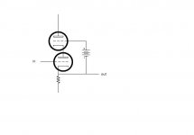
Stack another triode on top of the CF and drive its grid with the output, level-shifted so that the CF has enough plate-to-cathode voltage to operate. I'll see if I can find a Tektronix schematic that shows how it's done- it was a common trick for scope design back in the '50s and '60s.
edit: Here's a quick conceptual sketch
edit: Here's a quick conceptual sketch
Attachments
A normal cathode follower has a very high PSRR to plate voltage variations, meaning that the plate voltage can move around a lot without causing a serious change in the output as long as there is enough voltage for the tube to work. In a normal circuit the plate voltage must be high enough to so that the largest signals may pass unclipped. This means that there is usually a fairly large voltage across the tube. The plate voltage is usually fixed, and the cathode voltage varies with the signal voltage. The parameters of the tube vary slightly with the applied voltage causing small distortions of the signal.
Now suppose we could devise a circuit that moved the plate voltage in step with the signal voltage. Tha K-P voltage in the cathode follower would remain constant over all signal conditions eliminating these small distortions. Most agree that the small distortions created in the small signal cathode followers seen in typical audio designs are far below the distortion created in the output stages. The added complexity needed to "modulate" the plate voltage is probably not worth the effort.
But, what if we are designing a cathode follower output stage? Now we have the opportunity to design an output stage with virtually no distortion. Fixing the K-P voltage offers us another benefit. It is now possible to greatly reduce the power dissipated in the output tube.
How do we do this? The simplest way is to add another follower (tube or mosfet) between the output tube and the power supply and drive it with a shifted (zener diodes) version of the drive signal. It is also possible to design a complex SMPS do do the same job. I have built several versions of these circuits and they do seem to offer some serious improvements in an output stage at the expense of circuit complexity. I plan to post some of my circuits on my web site when I return from an impending trip, and have some time to document them. I am enclosing one of my simulation schematics to illustrate the technique.
This thread has made me aware of work done along these lines back in 1957 by J. Ross Macdonald. His work is centered on low power applications with very high input impedance (many megohms) and low output impedance (5 ohms) with very low distortion, all accomplished with 12AX7's and 5687's. These attributes are accomplished with multiple cathode followers and a feedback loop. I believe that this work can be used to create a very serious cathode follower output stage.
Read the Macdonald paper and decide if the added complexity of this circuit can be of use to you. The "cathode follower" that I am building contains 5 tube sections.
Attachments
- Status
- This old topic is closed. If you want to reopen this topic, contact a moderator using the "Report Post" button.
- Home
- Amplifiers
- Tubes / Valves
- augmented cathode follower?