go back to school
1) Joe, this isn't rocket science. This is one RC stage and one cathode follower. If you're questioning whether "this circuit even works" then you need to do a lot more reading.
2) You chose to branch off on your own with the PSU. That's fine, but then don't act like I don't know what I'm talking about. You did not build "my circuit", you built your own circuit. So go fix your own circuit then.
3) How about thanking me for my patience, with the 200 questions I've answered for you?
Joel

(Is that acceptable Dave???? I took all those horrible astriks out ******)
Originally posted by burnedfingers
Joel
How about some constructive ideas instead of telling me that I made a mistake?
...Does this circuit even work? Have you made this circuit piece for piece? I would gather that you haven't or you would soon see what I am running into.
1) Joe, this isn't rocket science. This is one RC stage and one cathode follower. If you're questioning whether "this circuit even works" then you need to do a lot more reading.
2) You chose to branch off on your own with the PSU. That's fine, but then don't act like I don't know what I'm talking about. You did not build "my circuit", you built your own circuit. So go fix your own circuit then.
3) How about thanking me for my patience, with the 200 questions I've answered for you?
Joel
(Is that acceptable Dave???? I took all those horrible astriks out ******)


Quote
You chose to branch off on your own with the PSU. That's fine, but then don't act like I don't know what I'm talking about.
Actually with the exception of the size of the transformer I built this project with the exact components as specified in the schematic. The transformer voltage was knocked down to 285volts and then down to 250volts for possible use of my 5692's. I would say therefore that I built "your" circuit considering the fact that I followed your schematic. I didn't happen to get "your" bias values so I don't consider it to be a viable working project.
Quote
you did not build "my circuit", you built your own circuit. So go fix your own circuit then.
Joel, considering the attitude you seem to display...keep it along with your "help".
dhean
I appreciate the offer to look at my wiring but unfortunately I unsoldered/scrapped this project this evening. Whatever this is worth I did make an error in the heater wiring as I didn't see pin nine and this error was corrected. With respect to the other elements, everything was in its proper place and of proper value.
The last thing I did with it this evening was to unsolder one side of the 6sn7 and check the bias voltage. With both sides paralled it was -7.00volts. With just one side of the 6sn7 running it had dropped to -6.23volts bias. I even tried other 6SN7's to see if their was a difference. The change between different tubes was less than .3volts.
Now, if we analyze the first section I am told that the bias should be -4.0volts on each section.with a grid resistor of 10K,100k plate resistor and a 1.6K cathode resistor. I come up with -2.0volts on each section.
I give up!!
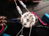
Looks to me like these pictures will show that pin one and 6 has a 100K resistor and a .1 soldered to it. Pin 2 and pin 7 are the grid resistors 10K that terminate to the volume controls. Pin 3 and pin 8 have the 1.6K(in my case they are within 5%)going to signal ground.
Now the PSU is resistored down for a final B+ of 285volts and even uses "Joel's rectifier tube"
Now, given the voltage is the same,resistors are within tolerance, connections are made per schematic, the circuit IF CORRECT should return the correct bias figures if indeed the figures themselves are correct. I still get aprox -2 volts bias for each section, I was told I should have -4.volts each side.
Now, the 6.3 volts is applied to terminal 9 and to paralled terminals 4&5.
More pictures
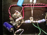
This is a somewhat crappy picture that will show that the correct resistors were terminated at the correct points per the schematic. It should also show that the tube sections are paralled.
You should see the following:
The tube sections are paralled 1&4,2&5,3&6 and heater on 7&8(note 6.3 volts here Joel) B+ is fed to pin 2 which is paralled to pin 5.
Pin 2 has a 470K resistor going to a terminal strip where it meets with the 470ohm 1 watt resistor from pin 3. At this junction point the 7.7K resistor connects and goes to signal ground.
I have the following:
I HAVE THE CORRECT HEATER SUPPLY>
I have the tube sections paralled.
I have the correct resistor values within spec.
I have the correct terminations.
I have the correct B+ as specified on "Joel's Schematic"
Conclusions that could be drawn....
Tubes could be faulty......tried a dozen with the same result.
Resistor values could be out of spec........would be more than happy to shoot pictures to prove values for the non believers.
Wiring is incorrect....................I think photo's will prove this incorrect.
Schematic itself could be faulty..............possibility
Bias target values could be incorrect.....possibility
I'm at a loss here gentlemen. Any worthwhile comment would be appreciated. As it seems that while this should work on paper it sure as hell doesn't in real life.
Attachments
More pictures
This is a somewhat crappy picture that will show that the correct resistors were terminated at the correct points per the schematic. It should also show that the tube sections are paralled.
You should see the following:
The tube sections are paralled 1&4,2&5,3&6 and heater on 7&8(note 6.3 volts here Joel) B+ is fed to pin 2 which is paralled to pin 5.
Pin 2 has a 470K resistor going to a terminal strip where it meets with the 470ohm 1 watt resistor from pin 3. At this junction point the 7.7K resistor connects and goes to signal ground.
I have the following:
I HAVE THE CORRECT HEATER SUPPLY>
I have the tube sections paralled.
I have the correct resistor values within spec.
I have the correct terminations.
I have the correct B+ as specified on "Joel's Schematic"
Conclusions that could be drawn....
Tubes could be faulty......tried a dozen with the same result.
Resistor values could be out of spec........would be more than happy to shoot pictures to prove values for the non believers.
Wiring is incorrect....................I think photo's will prove this incorrect.
Schematic itself could be faulty..............possibility
Bias target values could be incorrect.....possibility
I'm at a loss here gentlemen. Any worthwhile comment would be appreciated. As it seems that while this should work on paper it sure as hell doesn't in real life.
- Status
- This old topic is closed. If you want to reopen this topic, contact a moderator using the "Report Post" button.
- Home
- Amplifiers
- Tubes / Valves
- Joel's 6SN7 preamp (photo)