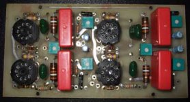
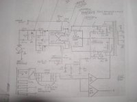
Does anyone recognize this ST-70 driver board? It has 4 wima .47 uf caps and I believe it takes four 6DG8 tubes. It has no markings on it what so ever. I am sure I could figure out how to hook it up but a schematic would sure make it easier.
Thanks in advance
Shane
Thanks in advance
Shane
Attachments
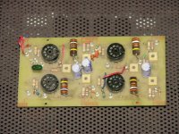
It looks similar to the "Tube God" board sold by the late Harvey 'Gizmo' Rosenberg. I have one in my parts pile (the first mod kit I ever bought!), it's close but not exact. Mine used turrets for the off-board connections, and the layout is similar but not exact. Maybe yours is a later version?
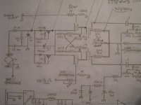
The circuit used 6DJ8's in a cascode differential amp. Similar to Curcio's circuit, but without CCS loading. I doubt that I still have a schematic.
Bill
The circuit used 6DJ8's in a cascode differential amp. Similar to Curcio's circuit, but without CCS loading. I doubt that I still have a schematic.
Bill
Pyre said:Has anyone a picture of Tube God Board?
From the depths of time, here's mine.
Attachments
So it turns out that it is indeed an Andy Fuchs board. I got an email back from Andy with a diagram and instructions on how to hook it up. Now that’s what I call customer service, supporting a product 20 years later that I bought for 10 bucks off eBay.
It sure does look very similar to the Tube God driver board. Maybe both were based on a similar concept that was popular at the time. I notice the Tube God board does not have any caps on the board. Were they taken off or not part of the circuit?
It sure does look very similar to the Tube God driver board. Maybe both were based on a similar concept that was popular at the time. I notice the Tube God board does not have any caps on the board. Were they taken off or not part of the circuit?
Quinnling,
I know Andy, and yes, he did work with Harvey back when. And yes, I do believe Brian Clark designed the board/circuit. It's a dual cascode 6DJ8 differential with cross coupling at the upper grids. The tail resistor went to a negative source derived from the 5V recitfier winding which wasn't used being replaced with SS diodes. At least in the version I saw.
I saw Andy earlier this year and he's manufacturing some nice looking tube guitar amplifiers in a facility not too far from his old GSI digs.
Victor
Pyre said:I notice the Tube God board does not have any caps on the board. Were they taken off or not part of the circuit?
The coupling caps (orange drops) were a bit large for the allowed space, so they're installed under the board.
Bill
the "skinny"
The boards were made and sold originally by NYAL, and later were sold by my company GSI, after leaving NYAL.
The original boards were based on a design by John Syder, and we later changed the circuit to include cross-coupling and a discrete constant current sources. That design work was done by Brian Clark.
We also made another board with a 12AX7 and a 6FQ7 as cascade diff pairs as well. I'd offer the circuit here, but it's in a notebook I cannot currently locate. I've moved a bunch of times since then (over 25 years ago), so forgive me if I don't have the data readily on hand.
If there's any serious interest, I would be able to replicate the boards and sell them but it looks like this market has shrunken to a small one !
Hey there
Should either of the last two posters need help (with HV regulator or GSI driver board), I can help.
Drop me a note: andy@fuchsaudiotechnology.com. I could make up a driver board or two fairly easily.
I could assist with the HV reg as well. it's a pretty simple series pass device using MJ-423's and I believe a TIP-50 and a zener string. Nothing fancy, but they worked well. If I were to make one today, I would likely use a Hexfet. I have used some devices that are 800-V 10 amp's and work well.
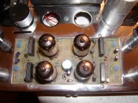
I managed to get one off ebay. Naturally it didn't work correctly and I repaired it and got it running again. I think it has way too much feedback as the information I received says the feedback resistor should be 100K and it has 20K. One of the problems the amp had was a broken feedback connection in the left channel which resulted in a louder signal. It sounded massive with no feedback.
Picture of the amp.
I don't know if I will keep the driver board in there or switch to one of my boards that is a rework of the 6SJ7 input and 6Sl7 long tail design with CCS. I would be interested in hearing of others opinions on the GSI driver board. Also, would performance gains be had by using HV regulator boards to power the driver board?
Attachments
FB resistors
The values depend on the power tubes used and the resistor on the grid to which the feedback returns (it's a differential front end with audio and feedback inputs). We used it with 8417's triode connected, as well as EL-34's and 7591's, so the FB values changed based on the tubes used.
I usually aimed for about 15 db of gain reduction from the feedback loop, as I recall. Still trying to find an accurate schematic in my archives. Heck, it's only about 30 years old....
I have been working on my ebay find with the GSI board trying to get the bugs out as its a classic example of killed by technician. I haven't seen soldering ability like it posesses since I let my 11 yr old grandson try to solder something.
I seem to be making progress slowly and its showing by its improved audio detail. I'm willing to keep working on it because its showing promise and I judged it harshly before I analyzed the errors that the prior owners made. I am told that it should be using photo flash capacitors but it has none. Is there a specific difference between them and standard caps?
Also the CCS circuit which I haven't examined yet contains 2) LM334Z which I have't seen or played with before. Is it one for each 6922? Would this design benefit from using DIYAUDIO current sources?
Could this design be modified to use other tubes? The 6FQ7 would really trip my fancy.


- Status
- This old topic is closed. If you want to reopen this topic, contact a moderator using the "Report Post" button.
- Home
- Amplifiers
- Tubes / Valves
- Mystery ST-70 Driver Board