I've just finished a power supply design using a Maida regulator and I'm having some difficulties. It does seem to be working properly except that there's still excessive ripple on the output. When I try to add extra capacitance before it or after it doesn't seem to change anything. Without proper equipment I'm at a loss to measure frequency etc.. of the ripple voltage, but I'm getting about 200mv of ripple from a 200V @ 80ma supply. Being new at these things I was wondering if there's any common mistakes or problems I could be making? I understand that I haven't been too specific about the power supply but any initial thoughts would be appreciated. Thanks.
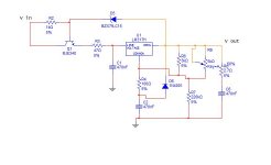
I've attached a JPEG of the circuit. I pretty much ripped the circuit right out of Morgan Jones's "Valve Amplifiers", though changed a few comonent values. I measured the ripple with a pretty run of the mill handheld multimeter. To be honest, not dropping enough voltage on the regulator sounds like something I could have over looked. I ran it through a spice simulation and when the voltage is under the drop out of the regulator it gives a ripple waveform close in voltage to what I'm measuring. Unless any other glaring errors are apparent in the circuit, that's probably what's going on. Unfortunatley I won't even be close to the board until the weekend so I won't know until then. Thanks for the help!
Attachments
Andrew,
Any luck?
SY,
I am about to build one for a 300VDC B+ for my common cathod 12B4 preamp. I have got Morgan Jones's book.
So what can go wrong? Would you please recommend the most reliable, simple version / variation of the Maida reg with its schematic?
I would like to keep things as simple as possible, so if I don't have to build the relay part of the circuit I would avoid it. What worries me at this stage is how the Maida reg would behave when the amp is turned on while the tube is still cold if no relay is used. I presume when turning off there would be no problem.
Your advice will be much appreciated.
Regards,
Bill
Any luck?
SY,
I am about to build one for a 300VDC B+ for my common cathod 12B4 preamp. I have got Morgan Jones's book.
I've built dozen of Maida regs and have seen most of what can go wrong
So what can go wrong? Would you please recommend the most reliable, simple version / variation of the Maida reg with its schematic?
I would like to keep things as simple as possible, so if I don't have to build the relay part of the circuit I would avoid it. What worries me at this stage is how the Maida reg would behave when the amp is turned on while the tube is still cold if no relay is used. I presume when turning off there would be no problem.
Your advice will be much appreciated.
Regards,
Bill
The number one thing that goes wrong is operator error- a slipped scope probe has killed quite a few pass devices in my lab.
Number two is insufficient minimum current for regulation. 5mA is typical, but some regs seem to need a bit more. That's what you have to pay attention to for startup- a divider string and bleeder combo that takes you over 6-7mA will insure that the reg will start cleanly even with cold tubes.
Number three is insufficient voltage across the regulator (too much is fatal, too little ruins performance). The regs that MJ used in his projects are exemplary, but the one he uses as the basic example has a big problem in this area- the Zener needs to be more like 12V for that circuit.
Number four is output bypassing. For stability's sake, I tend to use a small resistance in series with the output cap. Without it, I've had some oscillation with certain capacitance values.
Number five is insufficient attention to power dissipation ratings, especially the set resistor and the heatsinking of the pass transistor. There are some cool tricks (like a resistor bypassing the reg) to minimize the pass device dissipation- don't hesitate to use them.
Number six is layout. The resistor at the top of the divider needs to be VERY close to the 317.
Number seven is the adjustment potentiometer- running DC through a wiper is not conducive to reliability, so it's best to try to keep that current low. In the Maida reg from the Red Light District, I used the trimmer in series with a large resistor as a parallel trim to the set resistor- the set resistor used about 80% of the set current, reducing the stress on the trimmer's wiper.
Wow! Thanks, SY.
In MJ's book, 470n is used as the output cap and there is a 2R7 in series.
Is your "small resistance" larger or smaller than 2R7? What do you think to be the optimal value for the output cap and the series resistor?
Regards,
Bill
Number four is output bypassing. For stability's sake, I tend to use a small resistance in series with the output cap. Without it, I've had some oscillation with certain capacitance values.
In MJ's book, 470n is used as the output cap and there is a 2R7 in series.
Is your "small resistance" larger or smaller than 2R7? What do you think to be the optimal value for the output cap and the series resistor?
Regards,
Bill
The optimal value will be different, depending on the use, but MJ's values are not unreasonable. I like to swamp the output for best stability, so I use caps in the 20-50uF range, with series resistors of 3-10R. I'll optimize it experimentally if it's critical, otherwise, it's just 47u/4R7 just out of habit and because those values always work at least acceptably.
Thanks again, SY. I am now ready to buy the parts and build it.
The LCRCRCRC PSU has served more than a year but I have found a problem with it so it will be replaced. I am now convinced that regulated PSU is better.
Regards,
Bill
Brett: from your past posts your favourite PSU is GP's CCS - shunt reg. It would be interesting to compare the Maida with that and see if there is any difference to the 12B4 circuit.
I think the shunt reg if well implemented would have the edge. In my differential ccts I don't recall hearing a massive difference, certainly not worth the stuff around it involved. In low level cct like an RIAA, I'd go CCS/shunt. I had my RIAA's and pre all in the one case, so I used them everywhere.HiFiNutNut said:Brett: from your past posts your favourite PSU is GP's CCS - shunt reg. It would be interesting to compare the Maida with that and see if there is any difference to the 12B4 circuit.
My Maida Regulator
I am building a B+ power supply for a powerful tube amp I am making. The design is supposed to supply 360 volts into a 750mA load (720 with the 500 ohm Rload). What I am concerned about is my new RadioShack volt meter, when I set it to AC volts, says there is about 35.35 VAC across Rload. On DC, the meter fluctuates little to none, reading almost a dead on 360.0 volts.
I may have ruined the meter somehow because I accidentally placed the microammeter in parallel with the Rload (moved the switch) and the fuse blew (the fuse does affect the volt meter). I wonder if the AC meter was damaged at all when this happened. My previous meter I did the same thing with years ago. I can be careless, but the meters should be more idiot proof than just a fuse.
Anyway, when I get back to school I will test it with my good Fluke meter, and I have access to a high end HP unit as well.
Is the 35 volts is really there or is the meter giving a fallacious reading? I will try scoping the output tomorrow. If the 35 volts is there, why? I have the following setup:
- 300 volt transformer secondary winding, feeding a full wave bridge. That is about 424 volts minus the ripple and diode drop feeding the regulator, which should be more than enough.
- 100uF filter cap. More capacitance on both the input and/or output does not eliminate the 35 VAC reading.
- The transistor and regulator are heatsinked, as they become warm.
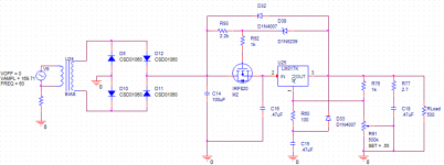
- The schematic of my setup is attached.
- The dummy load I am using is two 1k ohm 225 watt resistors in parallel. They get as hot as a heater, i know.
I am building a B+ power supply for a powerful tube amp I am making. The design is supposed to supply 360 volts into a 750mA load (720 with the 500 ohm Rload). What I am concerned about is my new RadioShack volt meter, when I set it to AC volts, says there is about 35.35 VAC across Rload. On DC, the meter fluctuates little to none, reading almost a dead on 360.0 volts.
I may have ruined the meter somehow because I accidentally placed the microammeter in parallel with the Rload (moved the switch) and the fuse blew (the fuse does affect the volt meter). I wonder if the AC meter was damaged at all when this happened. My previous meter I did the same thing with years ago. I can be careless, but the meters should be more idiot proof than just a fuse.
Anyway, when I get back to school I will test it with my good Fluke meter, and I have access to a high end HP unit as well.
Is the 35 volts is really there or is the meter giving a fallacious reading? I will try scoping the output tomorrow. If the 35 volts is there, why? I have the following setup:
- 300 volt transformer secondary winding, feeding a full wave bridge. That is about 424 volts minus the ripple and diode drop feeding the regulator, which should be more than enough.
- 100uF filter cap. More capacitance on both the input and/or output does not eliminate the 35 VAC reading.
- The transistor and regulator are heatsinked, as they become warm.
- The schematic of my setup is attached.
- The dummy load I am using is two 1k ohm 225 watt resistors in parallel. They get as hot as a heater, i know.
Attachments
With that kind of current draw, you're going to want a heftier pass device than an IRF820. You may also need to bypass some of the current around the reg using a power resistor to keep the pass transistor dissipation down and keep the 317 farther away from its current limit.
To see what's happening at the output, you need an oscilloscope, otherwise, you're working blind. And that's a pretty dangerous neighborhood to be in without being able to see.
To see what's happening at the output, you need an oscilloscope, otherwise, you're working blind. And that's a pretty dangerous neighborhood to be in without being able to see.
Sy, in your experience, what's the minimum drop-out voltage these "Maida" regulators will operate at? Also, what causes you to recommend using a 12 V zener rather than the 6.2 V used in the original National App Note?
It depends on the pass device and the amount of ripple. The dropout is also dependent on the series resistor- note the issue with the rated current and dropout with the originally published schematic. If memory serves, the 317 has a dropout somewhere around 3V, add the Zener voltage minus a Vbe drop (for a bipolar pass device), and then add the raw supply ripple to get an estimate of dropout.
I try not to push dropout, and in tube circuits there's usually volts to burn, so there's no penalty for using a 12V diode; that provides a comfort margin for Nervous Nellies like me.

SY: Sounds like we're doing the same math. Worst case drop-out for the National LM317 is 2.5 V over temp. Most Maida regulators use a Darlington pair, so there's two Vbe's there. Plus the IR drop through the series resistor on the input of the LM317.
How much current do you generally run through the zener diode? I'm currently looking at 1~2 mA and I think that's a little skimpy. Yet, burning more means burning more power in the series resistor for the zener... Tradeoffs, tradeoffs.
~Tom
How much current do you generally run through the zener diode? I'm currently looking at 1~2 mA and I think that's a little skimpy. Yet, burning more means burning more power in the series resistor for the zener... Tradeoffs, tradeoffs.
~Tom
The number one thing that goes wrong is operator error- a slipped scope probe has killed quite a few pass devices in my lab.
There's great truth in that statement! Why, just this evening I did some "welding" while checking B+ voltages on a tube amp. Managing one probe is reasonable. Placing two while trying to read two separate meters at the same time is challenging!
- Status
- This old topic is closed. If you want to reopen this topic, contact a moderator using the "Report Post" button.
- Home
- Amplifiers
- Tubes / Valves
- Maida regulator