G'Day again.
After the success of my first tube amp build, a TubeLab SimpleSE, I decided I had to get my teeth in to this and build another amp. The amp will be for my girlfriend to use in her office, with the signal source being her computer. I am also going to build a set of bookshelf speakers to go with the amp, probably Fostex FE127E in small bass reflex box. For the amp build, I was thinking of something small, simple and single ended, but my father, an electronics engineer, convinced me to try something a little more complex. After a little trolling online he suggested that this would be a good project, Mullard ECL82 push-pull:
http://www.bonavolta.ch/hobby/en/audio/ecl82_2.htm
We decided to modify the design slightly, solid state rectification, no input tone controls, and a slight change to the feedback resistor to take in to account the chosen output transformers - Edcor XPP10-8-8K. As this is for a small office, size was a consideration, so I was ambitious and purchased a Hammond 10*6*2 enclosure. The particular Edcor transformer was chosen as it will fit under the chassis.
Have purchased all of the parts and now would like a little advice on the point to point wiring. I have read the posts regarding grounding schemes, and these have been very informative and helpful, but my search for a point to point wiring guide/tutorial has not been successful. If anybody could give me a few rules of thumb, tips, suggestions or point me in the right direction on the web I would be very grateful.
Thanks,
Chris
Thanks Sy,
I love to have a book to browse through, much better than staring at a computer screen. I have ordered the book, but what am I to do while I wait") As I live in Australia, I was limited to the sources I could find to get the book. Found an online store that had one in stock, but they say allow 6-10 days delivery
As I live in Australia, I was limited to the sources I could find to get the book. Found an online store that had one in stock, but they say allow 6-10 days delivery
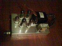
Any tips to get me started? It would be nice to be able to start getting the chassis ready and bolting the big items on. Basic plan is to have the power transformer and choke next to each other at the back of chassis on top, output transformers at back under the chassis, with power, choke and output cores 90 degrees to each other. Input ECC83 at front centre with the four 6BM8s just behind. Volume pot on the front near the driver tube. Any obvious problems with this basic setup while I wait for the book?
Here is basic picture, sorry for bad quality, using phone camera today...
Thanks,
Chris
I love to have a book to browse through, much better than staring at a computer screen. I have ordered the book, but what am I to do while I wait
As I live in Australia, I was limited to the sources I could find to get the book. Found an online store that had one in stock, but they say allow 6-10 days delivery Any tips to get me started? It would be nice to be able to start getting the chassis ready and bolting the big items on. Basic plan is to have the power transformer and choke next to each other at the back of chassis on top, output transformers at back under the chassis, with power, choke and output cores 90 degrees to each other. Input ECC83 at front centre with the four 6BM8s just behind. Volume pot on the front near the driver tube. Any obvious problems with this basic setup while I wait for the book?
Here is basic picture, sorry for bad quality, using phone camera today...
Thanks,
Chris
Attachments
Hi Chris,
Here is a link to some photo's of some DIY valve amps.
http://www.triode-systems.com/modules/myalbum/viewcat.php?cid=7&num=5&orderby=ratingD&pos=5
My best tips 1) watch out for cold solder joints! Do learn how to solder properly. 2) keep the signal lines away from any A.C. voltage lines ((including the heater supply lines) 3) in areas where the signal lines get around (or near) A.C. voltage they need to cross at 90 degrees from one another. I like to use shielded signal lines where available and in areas where the audio signal is low (such as on the input).
Hope this helps a bit.
And here's an EL84 amp that I built:
http://www.diyaudio.com/forums/showthread.php?postid=1154718#post1154718
http://www.diyaudio.com/forums/showthread.php?postid=1138851#post1138851
http://www.diyaudio.com/forums/attachment.php?s=&postid=1139090&stamp=1171894873
Nothing fancy or novel, but proper attention to grounding, routing, and layout resulted in a very quiet and stable amplifier.
don't forget to stock up on terminal strips with different number of lugs. Antique Electronic Supply has a good selection. You can also go the turret board route for a cleaner look. P2P wiring always takes longer than you imagine - so be patient when you get to it.
Before you do any wiring, decide on how you will lay out your grounding, filament wiring, components, etc - I like to make a printout of the chassis (I use Front Panel Express) and use that as a basis.
Before you do any wiring, decide on how you will lay out your grounding, filament wiring, components, etc - I like to make a printout of the chassis (I use Front Panel Express) and use that as a basis.
SY said:I don't know about web sources, but if you're going to do it right, pick up a copy of "Building Valve Amplifiers." It covers layout and wiring issues very thoroughly.
I definitely second Morgan Jones' book, it's a good starting place for these sorts of things. Lots of practical advice and good suggestions for doing metalworking.
My best advice would be to take your time and not get in a rush. Make sure you have good quality tools. Start with a sketch if it helps (it often does) and don't be afraid to revise/improve upon it. If you start to get frustrated while building the thing, take a break and just walk away. I find that I make my worst mistakes (read: the ones that are the most expensive) under duress... Good luck and hope your build goes smoothly!
Thanks for the suggestions guys. Yes I have ordered the book, but it will take about a week to get here. Just about cleaned the local Jaycar shop out of tag strips yesterday
My initial plan of attack was going to be
1. Lay out filament wiring, twisted and placed in corner of chassis opposite side toshielded run of signal wire from back RCAs to pot.
2. Ground bus from back to front pretty much central to chassis, following connection suggested in posts on this forum.
3. Wire power supply from transformer to output tubes to input tube, in stages checking voltages as each stage completed.
4. Signal wiring starting with input tube then working down signal path.
Is this a reasonable approach? Hoping that this way any problems that occur will be a little easier to diagnose as I progress.
Thanks for the help so far. Hope I have not been too much of a pain with the questions while I wait for the book to arrive.
And the photos of other peoples amps? Hmmm, some of that work is so good it will probably make me embarrassed to post my efforts! How do you guys get the layout and wiring so neat?
Cheers,
Chris
Originally posted by chrish
And the photos of other peoples amps? Hmmm, some of that work is so good it will probably make me embarrassed to post my efforts! How do you guys get the layout and wiring so neat?
Cheers,
Chris
One thing I do when trying to figure out the layouts is to simply draw them out on sheets of paper. I get a sheet of paper, mark out the edges of the chassis along with where the major parts such as transformers and input/output jacks are mounted, then I pencil in the tubes and parts and figure out how run the wires to all of them. It usually takes quite a few sheets of paper before I get it right.
Funny about that, I wail and gnash teeth when I look at stuff from some of the other veterans here! In my case, I like to build and test things as modules, then bolt all the modules together. As you can see from my photos, my ground bus is run very much the way you propose. the only other "tricky" thing I did was to use a turret board with sockets.
Front Panel Express is a godsend to klutzes like me.
Front Panel Express is a godsend to klutzes like me.
Looks OK to me. I think it helps to use solid rather than stranded wire. Solid wire can be bent into shape and is reasonably rigid. Of course, keep leads short where possible. Use screened leads when you have to (but not to the extent that you introduce too much unwanted capacitance and lose high frequency signals).Is this a reasonable approach?
I also think there's a difference between the approach to wiring when you're still developing the amp as opposed to the finished article. I abhor breadboarding, which I find messy, error-prone, potentially hazardous and likely to introduce problems of its own through far-from-optimal layout. For that reason, I develop directly on the chassis.
I'm not interested in building someone else's already proven design, so I try to design and develop my own amp, with the help of LTspice modeling. A consequence of this is that I've 'enhanced' and rearranged it so much that it's now time to strip it right down and rebuild it from scratch, replacing small components like resistors as necessary and making sure all joints are secure and well-soldered.
Thanks for your help everyone, greatly appreciated.
One further question if I may...
If I was building this amp for my own personal use, I would include a standby switch. As this amp is for my girlfriend, I suspect that a little while after explaining how the amp works, she will most likely forget what I have told her and end up just leaving the standby switch in the 'play' position and just use the on/off switch. With solid state rectification will this drastically affect the life of the tubes? I am thinking that if the standby feature will not be used, it would be easier to simply not incorporate it. Suggestions?
Thanks again,
Chris
The usual wisdom these days is that it does no harm to tubes if the B+ is applied before they warm up, so long as the B+ in question is under 1,200 volts.
However, big surges can occur with SS rectification when the caps in the PS charge up on switch-on. A slow start is perhaps more beneficial than a delayed start. Maybe a thermistor (negative thermal coefficient resistor) in the primary of the power tranny would help. It would also help protect tube heaters from switch-on surge due to their low cold resistance.
However, big surges can occur with SS rectification when the caps in the PS charge up on switch-on. A slow start is perhaps more beneficial than a delayed start. Maybe a thermistor (negative thermal coefficient resistor) in the primary of the power tranny would help. It would also help protect tube heaters from switch-on surge due to their low cold resistance.
ray_moth said:I abhor breadboarding, which I find messy, error-prone, potentially hazardous and likely to introduce problems of its own through far-from-optimal layout. For that reason, I develop directly on the chassis.
Hey Ray what about this one....this amp was used on stage and it went wrong and LOOK what I found it up-ended ?
This isn't my work.....but someone offered me a good reward and I will put it back right.. ??
 To Chrish ......please don't do it like this !!
richj
Attachments
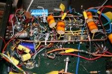
A pic of organised component routing. Large power amps (this one 200+200W) can end up heavily component densed using solder tags (RS components stock number 433-775) are still around. The large 3.5mm dia earth bus is seen to the left up and over,across the centre and overall signal component symmetry with phasesplitting bandolier of 39K power resistors. The reliability of this type of ciruit relies alot on the quality of soldering which has to be high. Everything is fixed in situ, some cable tying and voltage lettering.
Any pcb can be placed vertically, i.e DC heater supplies.
Despite considerable crowding, signal at the top and power section below this twin is capable of exemplary performance.
richj
Any pcb can be placed vertically, i.e DC heater supplies.
Despite considerable crowding, signal at the top and power section below this twin is capable of exemplary performance.
richj
Attachments
No different to servicing a Tektronix 545 mainframe hulk ? Built for battlework. True that amps need not be dreadfully complicated and oresome but with pricy output tubes I build in alot of protection thus the relevant wiring goes up.
Chrish; I'm a bit inclined to try the idea of a 555 timer ic with a relay as an idle time out. One always forgets switches and to leave a tube amp on idle is a waste of electrons.
I seem to remember Italian manufacturers were the first to introduce equipment with toggle switches that the "off" was always down and "on" up ? Who's responsible for this daft idea ??
richj
Rich,Hey Ray what about this one
That is exactly the kind of thing I end up with if I'm not careful!
That's why I say it's time I tore it down and rebuilt it properly, now that I've got it all working nicely. I heard somewhere that it was considered safer to do it that way, because accidentally bumping into/leaning on a toggle switch was considered to be more likely to knock it down than up. It was thus considered safer if 'down' was 'off'. I also heard that it had become standard military practice.toggle switches that the "off" was always down and "on" up ? Who's responsible for this daft idea ??
Hi rich ,
A daft idea or not . In my all assemblies , I ALWAYS
have left the “ OFF “ position of toggle switches , down .
I think it is more safe and easy to remember ( at least for me ) .
A LOT of manufacturers adopt this " convention " , too , not
only the Italians .
Carlos
A daft idea or not . In my all assemblies , I ALWAYS
have left the “ OFF “ position of toggle switches , down .
I think it is more safe and easy to remember ( at least for me ) .
A LOT of manufacturers adopt this " convention " , too , not
only the Italians .
Carlos
- Status
- This old topic is closed. If you want to reopen this topic, contact a moderator using the "Report Post" button.
- Home
- Amplifiers
- Tubes / Valves
- Point to point wiring help