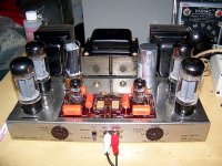
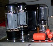
I have a question I know someone here has a answer for me. I just finished rebuilding my 2nd Dynaco ST-70 and although I have a complete set of EL-34's and 5AR4 tubes for it. I decided to put a quad of Sovtek 6L6WXT to try them out. I also plugged in a NOS RCA 5R4GYB to drop the plate and bias voltage a bit.
I measure 367 volts on the plates of the 6L6WXT tubes and I can lower my bias to 1.1 vdc which comes out to 70.5 milliamps per pair or 35.35ma per tube.
Is this ok, or should I raise the bias a little bit to maybe 40ma or 45ma per tube?
I know the plate loading is different for the 6L6 tube vs. the EL34 tubes and I read somewhere the output will be a little lower which is OK by me.
Opinions anyone?
Thanks,
Sal Brisindi
Attachments
6L6WXT+'s allegedly can handle 30W on their plates just like any other 6L6GC. I don't know how much B+ you're burning off with cathode bias because I'm too lazy to get out my datasheet, but assuming zero losses to biasing, you can probably get away with feeding around 50-60mA to each tube. Do you have the upgraded PT that puts out 300mA? If so, this might be an interesting experiment.
edit: saw you just have non-extra-special WXT's. I'm not sure about the wattage but 80% of 20 is around 45mA, again not accounting for cathode bias losses.
edit: saw you just have non-extra-special WXT's. I'm not sure about the wattage but 80% of 20 is around 45mA, again not accounting for cathode bias losses.
SY said:That B+ seems awfully low. What did you do to the power supply? You should have at least 400V there.
I replaced the 5AR4 with a 5R4. With the 5AR4 the plate voltage was 401V but the lowest I could bias was 1.7V on the test point on the front of the amp which is about 54ma per tube.
I did upgrade the quad can from 30/20/20/20uf to 40/80/30/20uf and on the bias circuit I replaced the selenium rectifier with a diode and replaced the 50uf caps with 100uf.
I can replace a 10K resistor with a 15K in the bias circuit to give me more of a bias adjustment.
Soren, my ST-70 has the original power transformer in it.
Thanks,
Sal Brisindi
SY said:I didn't think the drop could be that much, but your result and running a PSUD2 sim convinced me. Why use that tube in a hifi amp? (I could see it in a guitar amp, maybe)
Sy,
I am just experimenting with different tubes just to have fun. If the 6L6WXT can handle 400v then I will leave the 5AR4 in.
Sal
Hmm, 401V with a 5AR4 and a stock Dyna transformer seems very low.
I've worked on more than a few (dozens actually) and typically at 200mA load current the B+ is around 480V with a totally stock supply. There are a few variations in that power transformer but 720VCT on a 120V supply is not unusual. What are you doing differently from the typical dyna supply? Meter ok?
I've worked on more than a few (dozens actually) and typically at 200mA load current the B+ is around 480V with a totally stock supply. There are a few variations in that power transformer but 720VCT on a 120V supply is not unusual. What are you doing differently from the typical dyna supply? Meter ok?
Looking at the Dynaco ST-70 building instructions, it says 410vdc per plate of the EL34, I am off by 9 volts, not so bad. I did measure my outlet and it was 114 vac. I connected a variac and brought it up to 117vac and now my plate voltage was 405vdc, close enough by government standards.. ")
I used a Fluke 8060 DMM which is accurate and I measured the plate voltages with other meters with the same results (give or take a volt here or there).
Regards,
Sal Brisindi
I used a Fluke 8060 DMM which is accurate and I measured the plate voltages with other meters with the same results (give or take a volt here or there).
Regards,
Sal Brisindi
Sal:
Your 6L6's are biased way too cool. The power supply will sag when the amp is pushed.
ST70's are supposed to be biased in Class A territory because current demands are fairly constant at that setting. I understand Hafler designed the ST70 this way to avoid the cost of a more expensive power supply, (i.e. one that could supply higher current peaks.)
Regardless, if you like how it sounds try connecting your speakers up to the next higher impedance setting.
Bubba.
All my output tubes are EL84, which means they're cheap (about $4 each for the Russian old stock variety). Most of my amps are old and in need of rebuilding, which means they have power transformers designed to run on 115 VAC (and power in my house is more like 125).
As a result, all my amps tend to run around 100% of rated plate dissipation (or sometimes even more). I'm not sure exactly what the rated dissipation is for the 6L6WXT. The plain jane 6L6 seems to be 20.5 watts. The 6L6WGB is listed at 26 watts. Another poster said the 6L6 family was good for 30.
At 35 mA on 367 volt plates, you're only 63% of the 20.5 watt rating. If the limit is 26 watts, then you're still not halfway there. If you believe the 30 watt limit, then your tubes are just loafing along.
Now, don't take any advice from me. I already pointed out that my tubes are nearly disposable. But, if it were me, I'd crank those 6L6WXT until they start to glow, and then turn them back a hair.
Regarding the "6L6 family" (RCA ratings):
Metal 6L6 and 6L6G: Max. Pa = 19W, Va = 360V, Vg2 = 270V
6L6GB and 5881: Max. Pa = 23W, Va = Vg2 = 400V
6L6GC: Max. Pa = 30W, Va = 500V, Vg2 = 450V
7581A: Max. Pa = 35W, Va = 500V, Vg2 = 450V
7027: Max. Pa = 35W, Va = 600V, Vg2 = 500V
(Added to above data, is that in case of UL, Vg2 max. can be the same as Va max.)
Then, however: The Russians are quite free with their numbering. The 6L6WXT and 6L6EH is supposed to be same as 6L6GC. Internal construction of NOS GE 6L6GCs shows somewhat more anode radiating area and a larger G1 heat radiator. Beware of 6L6s with innards mounted on a glass tongue but marked 6L6GC. They are not - they are 6L6GBs. One must also remember that Pa ratings suppose open 25 degrees outside temperature.
Thus I would regard the 6L6WXT as more than capable of working up to 500V (I have used them there). Regarding the Pa .... there is not much of a difference; if in doubt (and in Arizona), regard as 25W.
Last indicator: Look out for semi-circular slots in the mica mounting wafers, between the anode mounting pin and the rest - that is proof of a higher voltage rating. If no slots, no 6L6GC etc.
- Status
- This old topic is closed. If you want to reopen this topic, contact a moderator using the "Report Post" button.
- Home
- Amplifiers
- Tubes / Valves
- 6L6WXT in a Dynaco ST-70