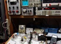
It works. Some twiddling with all of the knobs, and I get a nice sine wave on the scope. I tried tube current from 80 mA to 200 mA, and I tried several combinations of load impedances. The best results happen with a 4 ohm load on the 16 ohm tap on the transformer. That should work out to a 750 ohm load on the tube. The little UBT-3 transformer didn't like this too much, and I figure that I was loosing several watts in the OPT.
Power at the onset of clipping was 9.1 watts. The distortion is related to tube current. At 5 watts output I get 4.8% distortion with 80 mA of tube current. At 150 mA the distortion drops to 1.6% and at 200 mA the distortion is 1.1%. The output impedance is under 1 ohm, which is mostly OPT losses. The voltage drop on the primary was not nearly as severe as the secondary when switching from an 8 ohm load to a 4 ohm load.
I listened to it (in glorious mono) for most of the afternoon with both of my "8 OHM" speakers in parallel on the 16 ohm tap. The sound is awesome, solid bass, crystal clear highs....... I found that 80 mA sounded just as good at 200 mA except for some bass heavy music (Pink Floyd).
Attachments
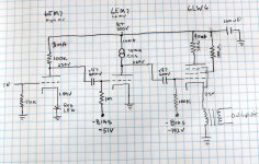
I suppose someone is going to ask for a schematic, so here it is. Before anyone rushes out to build this, let me explain a few things.
The driver is pretty straight forward. The input tube is the high mu section of a 6EM7. Just about any tube with enough gain will work here. Adjust the load resistor and tube current to match your choice.
The second stage requires a tube that can operate linearly at low plate voltages, and not explode as the plate voltage swings up to the supply voltage. The sweep tubes made for vertical (frame) output duty work well here, so this is why I chose the 6EM7. A 6DR7 (9 pin) will work well also. The CCS load is the key to developing a lot of voltage swing. A choke load should work also, but good chokes are not cheap and the CCS chips are.
The output section requires some thought. I used a 6LW6 sweep tube because I know how much abuse they can take without issue. The screen grid rating is 275 volts, I ran it all day at 550 volts. The plate dissipation rating is 40 watts, I had it at 80 watts for about 2 hours, and up to 100 watts for brief testing. At 80 watts there is no hint of plate or screen grid glow. At 100 watts the plate gets a dull red glow after about 2 minutes.
You need to choose a tube (or parallel combination) that can take this for extended time periods, you also need to plan the chassis for some heat dissipation.
Am I going to build one of these? Yes! First, I need to find a bigger OPT. Then, I plan to do some further testing. See those empty sockets, I plan to fill them up! I haven't decided which tubes yet, or just how much power it will make. I probably will settle for a reasonably powered SE cathode follower, but I plan to build an insanely powerful P-P cathode follower if all of my other circuitry works out.
I will do more testing on this circuit, and post updates as I find out anything useful.
Attachments
Hello
The disign off your 6lw6 amplifier his very interresting.
Problem : I'm supposed it 'll be difficult to find this valves in France.
It's easyer to find EL 504 EL 509 and EL519 or 6C33
I don't know "Audio Reality" bookand Bruce Rozenblitts disign 3x KT88
Someone can tell me more about this disign.
Thanks
yan
I´ve been thinking about building something like this for quite some time now. Possible tube candidates would be PL519 (perhaps more than one per channel) and a choke loaded 12B4A as driver stage.
With a few low Rp output tubes in // we could get away with a very low turns ratio in the OTP, possibly an autoformer if we can live with a fraction of a volt DC across the speakers.
I took this concept to its extremes in my latest project; 4xPL504 per channel working as cathode followers with only a ~0,5H choke as load, ie SE OTL. Sound is VERY good with the right speakers. Connecting the speakers to (imagined) centre taps on the chokes would change the load seen by the tubes and probably increase output power and the damping factor big time, but then it wouldn´t be OTL anymore...:/
By the way, PP cathode followers would work great with autoformers in the output stage since the DC offset would cancel.
Well, since I´m going to build an amp with 6AV5GA (Sylvania)soon perhaps this topology would be the way to go?
I will be using Hammond 125DSE output transformers, let´s say I wire them as 2,5K/8R with the secondary in series with the primary (auroformer) and feed the output tubes with about 250V plate-cathode and draw 70mA through the whole thing.
Together with a driver stage that can can deliver all the required voltage swing this should be up for 3-4 good sounding watts, maybe more.
Accordning to Sylvanias datasheet 6AV5GA can handle +-200V peak heater-cathode, so I think it would be possible to feed both channels from one heater winding which is referenced to ground.
Tubelab, I bet you have one or two things to say about this")
Cheers,
Daniel
I will be using Hammond 125DSE output transformers, let´s say I wire them as 2,5K/8R with the secondary in series with the primary (auroformer) and feed the output tubes with about 250V plate-cathode and draw 70mA through the whole thing.
Together with a driver stage that can can deliver all the required voltage swing this should be up for 3-4 good sounding watts, maybe more.
Accordning to Sylvanias datasheet 6AV5GA can handle +-200V peak heater-cathode, so I think it would be possible to feed both channels from one heater winding which is referenced to ground.
Tubelab, I bet you have one or two things to say about this
Cheers,
Daniel
Audio reality was a paperback book sold by Bruce Rosenblitt at Transcendent Sound several years ago. He now sells it in PDF format. The book has been reviewed several times on the internet. Some reviews are highly positive, while some are extremely negative. The material has a current copyroght, so I can not post the schematic. A "simplified" version can be found in this (positive) review:
http://www.tubecad.com/november99/page10.html
The opposite opinion can be found here:
http://www.enjoythemusic.com/magazine/equipment/1099/audioreality.htm
I bought the paperback book about 7 years ago, but I have not built any of the circuits. Maybe its the engineer in me, but I wasn't impressed with them. Some of his OTL amplifiers have received good reviews in the audio press.
When I set out to build last Saturdays experiment, I reached for my trusty old 6AV5, and thought about what I was going to do. I was planning to (and I did) explore the upper end of the power spectrum, so I put bach the 6AV5, and grabbed a 6LW6. These things laugh at power levels that would melt a 6AV5, I was running one tube at 190 mA and 525 volts. That is about 100 watts of dissipation.
This experiment proved that the concept is viable and that the 6lw6 is almost indestructable.
After looking over the test data, it seems that I was loosing about half of my power in the mismatched OPT. I need to experiment with a choke, and a resistive load bank.
These experiments will probably have to wait until I get back from a trip next week.
explore the upper end of the power spectrum
Well, I have a good bunch of Philips 813 transmitter tubes...

No, a power cathode follower with DH tubes that draws 10V 5A each of the filaments and requires about +-1kV of swing would be practically impossible.
First on the list will be to locate a pair of reasonably priced plate chokes for the drivers, I think vt4c.com has some interesting stuff.
Audio Reality
From the Tube CAD review, I picked up this error:
Fact is that "topology controls everything" applies to solid state design moreso than to hollow state. Solid state devices, particularly BJTs and power MOSFETs, are inherently high gain devices. Run a BJT at a very modest Ie= 1.0mA, and the resulting g(m) becomes: 38.46mA/V. (As for the MOSFETs, the g(m)'s are frequently stated in amps/volt.) There aren't a whole helluvalot of VTs with a g(m) that high. For BJTs, the only practical limit on g(m) is how much current you can force through it without melting the die.
The higher the gain, even if used in a low gain application, the more independent of the device characteristics the circuit performance becomes. So you won't find the sand heads doing things like swapping out transistors, not because it's more difficult than simply pulling a tube out of a socket, but because it doesn't really make any difference. VTs, being the low gain devices they are, circuit performance is more dependent on device characteristics as well as topology. You may get a different sound by trying different VTs, especially if NFB isn't involved.
Then there's this bit of self promotion:
I don't see any basis for a patent here. This thingy is simply a Futterman that uses an LTP splitter instead of a cathodyne. All he did was include cathode follower drivers to provide the same feedback that the original Futterman accomplished by returning the bottom of the cathode resistor to the output instead of to the DC ground.
Of course, you can patent anything, but I doubt this would stand up under a legal challenge. It's prior art.
When I see schtuffs like that, I get a little bit suspicious.
When I see Blackie Pagano complaining endlessly about how Rosenblit writes, and not addressing what he writes, I get a whole bunch of suspicious.
Hellzamatter Blackie, Rosenblit didn't slip you a little $omething under the table?
From the Tube CAD review, I picked up this error:
"Fully 99% of the sonic characteristics reside in the design. Circuit topology controls everything." This is not the prevalent view in the audiophile community, particularly with the fans of solid-state gear. As the solid clump of parts soldered to the circuit board neither admits ready comprehension nor easy modification, the solid-state fan's options are limited to accessories, such as line cords, speaker cables, and magic stones. When was the last time you heard someone say "Yeah, I swapped out the high hfe transistors in the differentially cascoded input to the amplifier with some low hfe ones and WOW the image is huge!" or even seen someone replace the output transistors with the same part but from a different manufacture to hear what they sounded like?
Fact is that "topology controls everything" applies to solid state design moreso than to hollow state. Solid state devices, particularly BJTs and power MOSFETs, are inherently high gain devices. Run a BJT at a very modest Ie= 1.0mA, and the resulting g(m) becomes: 38.46mA/V. (As for the MOSFETs, the g(m)'s are frequently stated in amps/volt.) There aren't a whole helluvalot of VTs with a g(m) that high. For BJTs, the only practical limit on g(m) is how much current you can force through it without melting the die.
The higher the gain, even if used in a low gain application, the more independent of the device characteristics the circuit performance becomes. So you won't find the sand heads doing things like swapping out transistors, not because it's more difficult than simply pulling a tube out of a socket, but because it doesn't really make any difference. VTs, being the low gain devices they are, circuit performance is more dependent on device characteristics as well as topology. You may get a different sound by trying different VTs, especially if NFB isn't involved.
Then there's this bit of self promotion:
The amplifier's design is straightforward except for the terminating the Cathode Follower's load resistor into the output. This is the critical design trick to the amplifier, as it is equalizes the gains between top and bottom tubes and the basis for Mr. Rozenblit's patent.
I don't see any basis for a patent here. This thingy is simply a Futterman that uses an LTP splitter instead of a cathodyne. All he did was include cathode follower drivers to provide the same feedback that the original Futterman accomplished by returning the bottom of the cathode resistor to the output instead of to the DC ground.
Of course, you can patent anything, but I doubt this would stand up under a legal challenge. It's prior art.
When I see schtuffs like that, I get a little bit suspicious.
When I see Blackie Pagano complaining endlessly about how Rosenblit writes, and not addressing what he writes, I get a whole bunch of suspicious.
Hellzamatter Blackie, Rosenblit didn't slip you a little $omething under the table?
I got this book when it first came out, and actually agree with SOME of what he says. He spends quite a few pages slamming the $300 power cord - magic stone - silver wired - titanium interconnect crowd. The second half of the book has his version of "correct engineering" complete with circuit diagrams. I don't agree with the designs exactly myself, but they did get me thinking about how I would do them differently.
The book does have an amplifier with a cathode follower output stage. The version in the book that I have uses 3 X 6550 in parallel. There is 5 pages of explanations about the design and theory some of whic does conflict with the text just a page before. There is a whole bunch of text devoted to designing for a low output impedance, which turned out to be 2.8 ohms, so 10 db of feedback was added. A cathode follower should be capable of better than 2.8 ohms without feedback. I don't understand why you need a cathode follower to drive a cathode follower. A properly designed cathode follower should have a high input impedance, and it should be nearly impossible to draw grid current.
What is required for these conditions to be met. Bruce points out that an output tube (or tubes) capable of enough peak current capability to drive a reactive load is required. He chooses 3 X 250 mA. Good, but I am looking for AMPS of peak current capability. This insures that the cathode is capable of going where the grid sends it. Then you need a lot of transconductance to be sure that the grid is capable of sending the cathode where it needs to go. If these conditions are met, then the driver determines the sound character of the amp. The cathode follower merely pumps up the current capability of the driver stage. I am still evaluating output stages, but a single 6LW6 has a 1.4 amp peak plate current rating. A 6336A (both sections) 800 mA with a transconductance of 26000. There are others that will work also.
I believe that the driver should be a circuit that you would listen to by itself as an SE amp. It should be optimized for maximum voltage swing. This usually means fixed bias. The circuit that I posted previously does pretty good, but I am sure that there are others that work well also.
I plan to optimize this cathode follower thing to death over the next few months. I have some rather unusual operating conditions, but most of what I am doing will be applicable to a standard amp.
I am leaving on a 2500 mile trip this weekend, so no new experiments will occur.
tubelab.com said:I got this book when it first came out, and actually agree with SOME of what he says. He spends quite a few pages slamming the $300 power cord - magic stone - silver wired - titanium interconnect crowd. The second half of the book has his version of "correct engineering" complete with circuit diagrams. I don't agree with the designs exactly myself, but they did get me thinking about how I would do them differently.
I agree with SOME of what Doug Self, Norman Crowhurst, Nelson Pass, &c say. I don't take anyone as having the last word. If I had this Rosenblit book, I'm sure it would be the same with that one as well.
I don't understand why you need a cathode follower to drive a cathode follower. A properly designed cathode follower should have a high input impedance, and it should be nearly impossible to draw grid current.
Even thought the common plate kicks Mr. Miller out of the picture, you still have the reverse transfer capacitance appearing across the input. Paralleling up a bunch of VTs might require active pull up for slew rate.
I am leaving on a 2500 mile trip this weekend, so no new experiments will occur.
Have fun.
the driver should be a circuit that you would listen to by itself as an SE amp. It should be optimized for maximum voltage swing.
Exactly what I´m doing here. Years ago I made a small SE amp with 12B4A as output tubes, parafeed with Hammond 30H 40mA chokes and 125C OPTs. Despite the cheap iron this amp sounds very good, so what I´m doing now is to copy the concept but this time I will use 40H 50mA chokes from vt4c.com.
Today I revisited the cathode follower test circuit that I posted earlier in this thread. I could only get 9 watts out of that amp during testing even when I cranked the tube dissipation up to 100 watts. That just isn't right. I suspected my grossly mismatched output transformer, which turned out to be the correct assumption. I was seeing almost 400 volts peak to peak across the primary, but only 9 watts out. With almost 300 ohms of DCR, all my power was just heating up the transformer.
So in order to find out what OPT I need, I eliminate the transformer, and test the amp without it. My normal procedure is to replace the OPT with a choke, and a parafeed cap, without the OPT. I then place power resistors in place of the OPT and experiment with the value to find the optimum load for the amp. If everything is connected to bench power supplies, you can adjust the plate voltage, the tube current, and the load impedance until you get exactly what you want. Then replace the resistor with the same value OPT. No load lines necessary!
I dug out a 55 pound choke that I have been saving for my SE OTL amp. It is 2 Henries at 2 Amps, with a 6 ohm DC resistance. I tried several different loads, and found that a 500 ohm load resulted in 30 watts output with the tube on the edge of redness. That is more like it. I settled on 600 ohms for the best balance of power, distortion, and tube life. I can get over 20 watts with conservative tube current, and 28 watts with the tube at 80 watts of dissipation. Without the limitations of the OPT you can measure the amplifier circuitry itself. Frequency response is 20 Hz (limited by the choke) to 95 KHz. Distortion is 0.9% at 5 watts rising to 5% at 28 watts.
Knowing this, I reached for the first transformer that I thought would get me 600 ohms. It is a Plitron P-P toroid OPT rated at 400 watts. I am using it in parafeed configuration, without a cap. The DCR of the choke is so low that I only have 2 volts across it, so I don't need a cap. I still get 28 watts, so the old OPT was just not working.
I have been listening to it for most of the evening, and it sounds good, too good. The best transients of any amp that I have built. Spooky real! Now I am going to need to buy some good 600 ohm SE OPT's because I just have to build one. The toroids are destined for a big P-P amp, and the chokes are just too big.
Tubelab, I have some 600 ohm SE transformers I was considering getting rid of, 15ohm DCR, 300mA. There the same as these.
http://cgi.ebay.com/600OHM-SE-AUDIO...ryZ73369QQssPageNameZWDVWQQrdZ1QQcmdZViewItem
Don't let the ebay fool you. I am very happy with these transformers performance and build quality. Sound excellent and frequency response was flat 20-20kHz(probably higher, but my analyzer only goes to 20k). I was debating starting a new amp with my pair, but kind of wanted to do an OTL for my next project. The only bad part about ordering them from that guy is that it took 4 months for them to finally get to me from Hong Kong. I may be willing to let my pair go for $100 shipped if your interested.
How about something really crazy: A class A2 SE DHT cathode follower amp?
I happen to have a quad of RCA 808 power triodes, I´ve collected them one by one over some time to build the coolest looking amp ever, or at least close to that...
Along with the 808s I´ve chased down some good looking driver and rectifier tubes (CV19 and RK60), all with one thing in common; dual top caps. I also have a pair of 3,5k 10W output transformers to go with these tubes.
808 is probably not the best audio power tube, the amplification factor is so high that they require positive grid bias to work in an SE amp. This is not a too big problem as I´ve worked with 811A before with some degree of success. What troubles me more is the need for 7,5V 4A "clean" DC for each of the filaments.
Can´t find any suitable switched power supplies and any linear design will be bulky and more or less expensive to build.
Here´s where the cathode follower idea enters the scene:
If there is less than unity gain in the final stage, AC heating should be possible without hum issues.
Let´s say I first balance away as much AC as possible with the usual resistive divider/wire wound pot arrangement, the remaining AC (hum) will be reduced by a factor 23 or something by the output transformer without first being amplified by the tube.
Such an amp would require a quite massive driver stage since it would have to both swing 500-600V p-p AND deliver "real" current to the grids. A choke loaded 12B4A cap coupled to a source follower might be able to do this, but it would have to be one heck of a mosfet...!
source follower might be able to do this, but it would have to be one heck of a mosfet...!
Nah. Actually you want the smallest mosfet that will do the job. The larger mosfets have too much capacitance. In a follower circuit the gate to source capacitance is not a problem since those two terminals "follow" each other. The important spec is "reverse transfer capacitance", or gate to drain capacitance. There are a few fets out there with outstanding specs. I use the Fairchild FQP1N50 for my designs, but it is only good to 500 volts. You need the 900 volt rated FQPF2N90.
Good luck with this design, and let us know how it works out. It is good to see someone doing something different. I still want to try some 6HV5's in cathode follower mode. Mu = 300, A2 is needed, but this must wait until I get back from a trip.
Thank you for your reply, Tubelab!
I´m not familiar with the FQPF2N90, can I use some IRF-device rated for 900V instead? I guess cascoding the mosfets would perform miracles against the capacitances.
A choke between souce and ground in the follower stage would eliminate the need for negative high voltage rail, perhaps an 30H 40mA Hammond unit would suffice if I cut the current through the choke down to 10-15mA. They work fine as plate chokes in my 12B4A parafeed amp, so there is some hope...
Otherwise I have a pair of 30H 200mA chokes but they would look silly as they are twice the sice of the output transformers.
The main question is if cathode follower operation eliminates the need for DC on the filaments or not. If not, there´s no reason to go through all the trouble designing a proper driver stage.
Another thing that I came to think of right now is that this topology might give the tubes a slightly longer life than what they would have in a regular amp: As the driver stage probably will be the limiting factor there´s no reason to run the output tubes at their maximum power capacity. These tubes are quite rare and expensive so I would feel very comfortable running them at say 20-25W plate dissipation rather than the allowed 35W.
I´m actually beginning to believe that using these tubes as cathode followers might be just the right way to go with them.
With their high Rp and unevenly spaced grid/plate curves they´re not the best choice for an SE amp anyway, as it would take a whole lot of NFB to get the distortion and output impedance down to useable levels.
I guess I have some breadboarding to to in the near future!
the only way to know if it will work, is to build it
Amen!
I have no mosfets around that can handle 900V but I do have some types rated for 400 and 500V, I guess I can build a low power/lowvoltage prototype to test the concept regarding the AC filaments.
- Status
- This old topic is closed. If you want to reopen this topic, contact a moderator using the "Report Post" button.
- Home
- Amplifiers
- Tubes / Valves
- 20W cathode follower amplifier