")
But I don't think light bulbs are terribly linear.
Yeah, there not. The resistance increases as power dissipation/heat increases. There almost a dead short when cold. Which is why I raise the question. Just thought it would be cool for bling factor, instead of just having some power resistor hiding in the chassis. It would take some experimenting for sure, to find the right bulb.
Just thought it would be cool for bling factor
Mo' betta bling would be a mercury vapor rectifier in the cathode circuit.
John
Use LEDs.
I should have been more specific, For an output stage, 60Vcg @ 250mA.
Mo' betta bling would be a mercury vapor rectifier in the cathode circuit.
Nice idea, if I can find any that meet the circumstance.
I was thinking lightbulb that's halfway lit so it glow's orange instead of bright. Kind of like in the ZEN amplifiers.
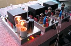
Not my amp. No idea if they are for the cathodes or not. You will notice they are part of the power supply section. They are used as slow regulators. more current = hotter filament = more resistance.
they end up about 3-5 times brighter than the tube filaments.
I suggest you experiment with a few different light bulbs, if you can't get close enough use a low value resistor to tweak the light bulb.
they end up about 3-5 times brighter than the tube filaments.
I suggest you experiment with a few different light bulbs, if you can't get close enough use a low value resistor to tweak the light bulb.
Attachments

Tungsten in the cathode = short life
The problem with light-bulbs or tube heaters in the cathode circuit is that when tungsten is cold, its resistance is low, and when it is hot, the resistance is high. This is a stabilizing effect, since the cathode bias would be increased as the current increases, but the problem comes during turn-on. When the amp is first powered-up, the output tube(s) have essentially no cathode bias, so as their cathodes begin to emit electrons, there is no current-limiting until the tungsten warms-up. You thus have a brief period of accelerated cathode-stripping, which will eventually destroy the cathode. This is worst when a tube heater is used as the cathode bias resistor, since there is more of a time lag.
On the other hand, I've seen light-bulbs used in the emitters of early germanium transistor power amps (specifically the Altec 351B) as protection devices. As you crank up the power in these class-B amps, the light bulbs get brighter.
With either tubes or transistors, there are the thermal lag effects, which change the sound of the amp according to the dynamics of the music.
- John Atwood
parallel?
then you could possibly put a "regular" small value resistor in series with the bulb to avoid the above mentioned cathode stripping. And another in series to make sure everything works if the bulb dies. The next (logical) step should be putting the cathode resistor back and wiring the bulb to the AC socket to illuminate the chassis.
then you could possibly put a "regular" small value resistor in series with the bulb to avoid the above mentioned cathode stripping. And another in series to make sure everything works if the bulb dies. The next (logical) step should be putting the cathode resistor back and wiring the bulb to the AC socket to illuminate the chassis.
That would not be the end of the world since it would stop the current flow.radtech said:I guess you'd also have to take into consideration the possibility of the bulb burning out, opening the cathode circuit.
Have you seen Nelson Pass' lightbulb-loaded follower amp?
http://www.passdiy.com/projects/zenlite1.htm
Pete
http://www.passdiy.com/projects/zenlite1.htm
Pete
I must agree with John Atwood (post #11).
The use of heaters as cathode bias was a moderately good idea in the olden days to get dc on the heaters and thus avoid hum there. In those times it was a real task to do it rectifier+filter-wise. Nowadays it is simplicity itself with semiconductor technology, should the need arise. For this reason and the factors mentioned by John I would not use it in this day and age.
The danger of an open cathode circuit is that the max. cathode-heater voltage could somewhere be exceeded.
Here is one that I am toying with. 6EM7 DC ala Kaufmann needs to drop about 150V at 50mA at the cathodes of the output section. Since it is SE there will not be much change in current and what there is will be so short in duration that the temp of the bulb won't really change. We need to tap off somewhere in the middle of the cathode resistor for the heater reference anyway so...
two 4W nightlight bulbs in parallel gives 1800ohms which drops 90V at 50mA. So on each cathode we parallel two bulbs and use a single power resistor in series to drop the other 60V. Connect the heater referrence at the junction and we have elevated the heaters by 60V for hum reduction.
The series resistor will prevent the tube initially being unbiased at turn on (though somewhat under biased) and the paralleling of the light bulbs means that if one burns out the other will increased the bias thus reducing current but not placing full B+ across the bypass capacitor.
I know that there is no really practical reason to do this but the hobby is about having fun right? What do you think.
mike
- Status
- This old topic is closed. If you want to reopen this topic, contact a moderator using the "Report Post" button.
- Home
- Amplifiers
- Tubes / Valves
- Light bulbs as cathode resistors?