Hi all,
I see a lot of different ways to connect the 300B cathode to ground in a fixed bias circuit.
- Some just connect a single resistor to one side (the 0V) of the filament http://my.execpc.com/~n9zes/300bamp.html
- Some use two resistors http://www.tubehifi.com/Circuit/C_106_300.jpg
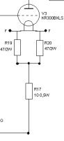
- Some use a combination (see picture, 2x47R to 10R)
If you use DC for the filaments, is there a 'best' way to connect the cathode, or doesn't is really matter at all? And isn't there some kind of inbalance issue with DC and fixed bias, because one side gets 5V and the other 0V?
Cheers, Ralph
I see a lot of different ways to connect the 300B cathode to ground in a fixed bias circuit.
- Some just connect a single resistor to one side (the 0V) of the filament http://my.execpc.com/~n9zes/300bamp.html
- Some use two resistors http://www.tubehifi.com/Circuit/C_106_300.jpg
- Some use a combination (see picture, 2x47R to 10R)
If you use DC for the filaments, is there a 'best' way to connect the cathode, or doesn't is really matter at all? And isn't there some kind of inbalance issue with DC and fixed bias, because one side gets 5V and the other 0V?
Cheers, Ralph
Attachments

CATHODE R
Hi,
The one shown in the first link has the cathode R connected to the wiper of the humbucking pot.so this is essentially the same as the one shown in the picture you show.
If you use DC to heat a DHT the humbucking Rs are dropped so if you still put a pot there it is only used to put the cathode R at the theoretical midpoint of the cathode.
Theoretical is the keyword since this will inevitably vary from tube to tube.
The combination you mention is actually the same as above but with fixed Rs.
Cheers,")
Hi,
The one shown in the first link has the cathode R connected to the wiper of the humbucking pot.so this is essentially the same as the one shown in the picture you show.
If you use DC to heat a DHT the humbucking Rs are dropped so if you still put a pot there it is only used to put the cathode R at the theoretical midpoint of the cathode.
Theoretical is the keyword since this will inevitably vary from tube to tube.
The combination you mention is actually the same as above but with fixed Rs.
Cheers,
Hi John,
Well don't shoot me, but actually, no. I see this only with auto bias circuit. I do however bypass it at the driver cathode.
Ralph
Edit:
Hi Frank,
I have connected it as we speak just like in my picture but understand that the two fixed resistors can be removed?
You ARE going to bypass the cathode resistor, aren't you?
Well don't shoot me, but actually, no. I see this only with auto bias circuit. I do however bypass it at the driver cathode.
Ralph
Edit:
Hi Frank,
I have connected it as we speak just like in my picture but understand that the two fixed resistors can be removed?
CATHODE R
Hi Ralph,
The two resistors are there to create a virtual midpoint,IME you can leave them out as long as the value of the cathode R is correct.
Any particular reason you want to leave the cathode bypass out?
This has consequences for the Rp and the OPT you know.
Cheers,
Hi Ralph,
The two resistors are there to create a virtual midpoint,IME you can leave them out as long as the value of the cathode R is correct.
Any particular reason you want to leave the cathode bypass out?
This has consequences for the Rp and the OPT you know.
Cheers,
Hi Frank,
The cathode R is approx 10 Ohm. There is no reason why I don't use a bypass cap at all, just didn't know I was supposed to be there And I'm not aware of any consequences when not using one.
My amp is loosly based on this one http://www.machmat.com/mysys/electric/images/kap2amp.gif.
But from your surprising faces I understand that I should use one. For the driver I use a 220uF/25V Black Gate. Maybe I could try one at the 300B cathode as well ...
Just did't know ...
Ralph
The cathode R is approx 10 Ohm. There is no reason why I don't use a bypass cap at all, just didn't know I was supposed to be there
And I'm not aware of any consequences when not using one. My amp is loosly based on this one http://www.machmat.com/mysys/electric/images/kap2amp.gif.
But from your surprising faces I understand that I should use one. For the driver I use a 220uF/25V Black Gate. Maybe I could try one at the 300B cathode as well ...
Just did't know ...
Ralph
CATHODE R
Hi Ralph,
Ah...but that is not the cathode resistor,it is not used to bias the valve but he put it there to track current flow through the outputvalve.
So no bypass cap required and if you're going to build the Kapittel it would be best to stick to this circuit,it seems well thought out.
I haven't checked what this Vaic tube really is but if you choose to use a *regular* 300B some adjustments will have to made.
Cheers,
EDIT: The AV-302B is actually a 300B with a 2V heater,interestingly this should go a long way in chasing the hum when fed from an AC supply.
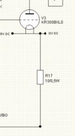
Aha Frank, I though that a resistor connected to the cathode was the cathode resistor, but I know what you mean You say: the 10 Ohm R is pretty useless there, but only to measure the voltage drop there (and figure out the current).
But combined with the info from Tim, I'll try different connections tonight, like this one (I really like as little resistors as possible there).
Cheers, Ralph
You say: the 10 Ohm R is pretty useless there, but only to measure the voltage drop there (and figure out the current).But combined with the info from Tim, I'll try different connections tonight, like this one (I really like as little resistors as possible there).
Cheers, Ralph
300B
Hi,
Choose something like 2*50 or 2*100 resistors of appropriate wattage.
Making the value too big will have little effect,too small and the heater will be a virtual short.
Cheers,
Hi,
Can I just use two the same resistors of any value?
Choose something like 2*50 or 2*100 resistors of appropriate wattage.
Making the value too big will have little effect,too small and the heater will be a virtual short.
Cheers,
- Status
- This old topic is closed. If you want to reopen this topic, contact a moderator using the "Report Post" button.
- Home
- Amplifiers
- Tubes / Valves
- Best way to connect 300B cathode