Hi,
I just got a Sears/Silvertone stereo tube amp. Its a 6BQ5 PP amp driven by 12AX7. The chassis# (model# ?) is 528.69240 .
I am trying to find more info about the amp. The schematic would be a good starting point. The connectors as you can see from the additional image links below are very unique. Probably they go into another console or something from which this amp was removed ?
I have kind of figured it out but would like to see some documented info.
The power transformer is tough. But not sure about the output transformers.
Would be nice to know some history of the amp. Like what year was it likely built and what type of unit/console could it have come from ?
An externally hosted image should be here but it was not working when we last tested it.
An externally hosted image should be here but it was not working when we last tested it.
An externally hosted image should be here but it was not working when we last tested it.
Like what year was it likely built and what type of unit/console could it have come from ?
The year is easy. There are visible date codes on the 6BQ5's and the filter cap. All are 1963. Sears sold several stereo consoles and this could have come from any (or likely several) of them. Some were phono only using a crystal (high output) cartridge in the turntable which does not require a phono preamp. This could have been the only chassis in the console. Some were elaborate consoles with a seperate AM FM stereo tuner chassis, a turntable and two way speakers all in a wood cabinet that was about 5 feet wide. This could have been the amplifier chassis out of either design.
My father bought one of the first Sears solid state consoles. A big unit that had all of the above features and storage for about 100 LP's, and crappy sound. When he passed away the stereo was (and still is) in the living room, but all of the records were gone

When he bought the stereo, I got the Magnavox mono (tube) unit, and made a guitar amp out of it. Been making them ever since.
This definitely came from a console that had another chassis (tuner ? preamp ?) because the white connector is basically voltage lines(heater, B+, other ac) going 'out' from the amp to ... something.
The 3 pin black connector is the input to the amp.
Last night I fired it up with the line-out of the CD player connected straight to the input and man that thing is loud! and those 6bq5's get hot! I definitely need a step atteneuator if I intend to keep using it this way! Those 10" wooofers of my not-so-senstive-and-very-tube-unfriendly-impedance-curve-diy-3-way speakers rocked the house!
I can't wait to get started on this one. After tracing the schematic I want to figure out the load line and the output transformer characteristics and then play around with it from there.
My first one was an Eico HF-14 but I didn't mess with it too much. I was on the lookout for a 6L6 PP amp and this just came along.
Oh by the way did you realize there is no rectifier tube ? Its a solid state diode rectifier! (in 1963 ?)
Oh by the way did you realize there is no rectifier tube ? Its a solid state diode rectifier! (in 1963 ?)
Percy,
Before Silicon diodes were available, Selenium rectifiers were widely used. You need to look underneath to see which type of SS rectification is employed. Selenium rectifiers are ticking toxic time bombs.
A Selenium rectifier looks like a stack of fins. If that's what you have, immediate replacement with modern Silicon parts is in order.Notice the filter cap. encased in cardboard. That strongly indicates a voltage doubler PSU is present. There is nothing inherently wrong with a doubler PSU. Some FINE units, like the H/K Cit. 2, Fisher 500C, and Marantz 8B, use voltage doubler PSUs.
All of the above are contemporary with your "Silvertone". FWIW, "El Cheapo" also uses a doubler B+ PSU.I mention "El Cheapo", because that vintage amp is an excellent candidate for conversion into an EC variant.
As stated above this unit may have selenium rectifiers. This is unlikely due to the current requirements of 4 6BQ5's. If it does they will be fairly large (1 to 2 inch) rectangular finned devices wired up to the power transformer. They do emit some toxic stink when they fry (smells like rotten eggs). They ALL will eventually fry. Replace them with silicon diodes.
This unit likely has early vintage silicon diodes. Some lower cost tube units in the early days of silicon rect used voltage doublers because the silicon devices could only handle a few hundred volts. Silicon diodes of that vintage usually looked like small "top hats" with a lead sticking out of each end. Glass encased silicon diodes came out about the same time this unit was made, so they could be present.
6BQ5's do get hot. The plate is much closer to the glass than in larger tubes. If in doubt about the rectifiers, post a picture of the other side.
This looks very similar to my 6V6 PP amp.
It also came from a Sears Silvertone console.On mine,the extra connector went to a preamp,and also had a couple 24Vac wires for a Turntable motor,IIRC. The connectors on mine look(ed) identical.
Hard to say,could go a preamp,or maybe a tuner?
The preamp that my little amp had was nothing special,even after some rebuilding.The power amp,after a rebuild,isn't bad at all!
Should make a good project!
DigitalJunkie said:This looks very similar to my 6V6 PP amp.
It also came from a Sears Silvertone console.On mine,the extra connector went to a preamp,and also had a couple 24Vac wires for a Turntable motor,IIRC. The connectors on mine look(ed) identical.
Hard to say,could go a preamp,or maybe a tuner?
The preamp that my little amp had was nothing special,even after some rebuilding.The power amp,after a rebuild,isn't bad at all!
Should make a good project!
Dude,
It looks like your 6V6 amp is an earlier tube rectified version of a basic concept, while Percy's EL84 amp is a later SS rectified version. I would not be surprised to find identical O/P trafos in both amps. The layouts sure are similar.
You say that 24 VAC are available at points U and V. That has favorable implications for a conversion into an "El Cheapo". That winding would be involved in the B- supply. In the 6V6 case, a switch to SS B+ rectification should put the rail voltage in the ideal range. Phase up the 5 V. and 24 V. windings and connect them in series. Bridge rectify with 4X 100 PIV Schottky diodes and CRC filter the "raw" B-. In the EL84 case, voltage double the 24 VAC with 2X 100 PIV Schottky diodes and CRC filter to get the B-. A booster toroid, like Scott M. used in his "El Cheapo", would augment the OEM rectifier winding.
Re: resistor on output transformer
Robert,
Those resistors are 160 Ohms and seem to be 1 W. size. Some possibilities are: an anti-ringing measure, an insurance load, or in series with headphones. 160 Ohms does not match the NFB circuitry of the 6V6 amp and the 6V6 amp's circuitry should be close to that of the EL84 amp.
A schematic, like DJ linked for the 6V6 amp would help.
Robert McLean said:I am curious about the resistor on the output transformers. What is it for ? If it is in series with a capacitor then I understand it, but I dont see a capacitor. Maybe there is a capacitor out of sight ?
Robert,
Those resistors are 160 Ohms and seem to be 1 W. size. Some possibilities are: an anti-ringing measure, an insurance load, or in series with headphones. 160 Ohms does not match the NFB circuitry of the 6V6 amp and the 6V6 amp's circuitry should be close to that of the EL84 amp.
A schematic, like DJ linked for the 6V6 amp would help.
actually its 150 ohms. and its simply in parallel with the opt sec.
and there are two diodes (VFZ2743J) and they are not sellenium.
the closest I have come to finding a schematic for this amp is a bunch of schematics for silvertone amps here -
http://www.schematicheaven.com/bargainbin.htm
http://www.doctoraudio.us/Silvertone/schematics.html
but I didn't find one for this amp. I have yet to go thru all of them though.
This person has it listed but have yet to hear from him - http://www3.telus.net/public/vintage1/tube.htm#s .
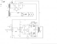
Ok, here's a closeup of the psu side of the underbody. You should be able to spot those two aluminium diodes. One of them has a .005uf cap in parrallel with itself and is going to the ground of the aluminium can cap(lower right corner). The other goes straight to black cardboard cap(upper left corner). I am not sure yet whether its a voltage doubler or not. Or whether power trans is center tap or not.
and there are two diodes (VFZ2743J) and they are not sellenium.
the closest I have come to finding a schematic for this amp is a bunch of schematics for silvertone amps here -
http://www.schematicheaven.com/bargainbin.htm
http://www.doctoraudio.us/Silvertone/schematics.html
but I didn't find one for this amp. I have yet to go thru all of them though.
This person has it listed but have yet to hear from him - http://www3.telus.net/public/vintage1/tube.htm#s .
Ok, here's a closeup of the psu side of the underbody. You should be able to spot those two aluminium diodes. One of them has a .005uf cap in parrallel with itself and is going to the ground of the aluminium can cap(lower right corner). The other goes straight to black cardboard cap(upper left corner). I am not sure yet whether its a voltage doubler or not. Or whether power trans is center tap or not.
An externally hosted image should be here but it was not working when we last tested it.
One HV lead from the power transformer goes to the junction of the two diodes. One diode goes to ground, the other goes to the floating capacitor. It looks like the other HV transformer wire goes to the negative side of the floating capacitor, and to the positive side of one section of the multisection capacitor. This is a classic full wave voltage doubler. There is probably no center tap.
Percy,
The presence of a single snubber cap., along with cathode to anode wiring of the diodes, confirms the PSU is a voltage doubler. Replace the OEM diodes with UF5408s. Replace the snubber cap. with a 10 nF. part rated no less than 1 KWVDC. A 2 KWVDC AVX brand part from Mouser is not at all expensive and you'll have peace of mind.
All electrolytic caps. must be replaced. LARGE value 'lytics in the doubler stack keep the rail voltage up and suppress the ripple fundamental, but they generate ripple overtones ("hash"). A choke between the doubler stack and the 2nd filter cap. suppresses the "hash." Available space may prevent the use of a "typical" PSU choke, but Mouser stock # 542-5900-103-RC (a 10 mH./250 mA. part) will fit and kill the higher order overtones.
Sorry about the "fat finger" error in resistor value. IMO, a safety load seems the most likely reason for those parts.
If the OEM signal topology is retained, the Carbon composition resistors have to be checked for drift outside of tolerance and all ceramic caps. in the signal path need replacement with film parts. Replacing grid leak resistors with metal film parts is a good idea, as noise will be reduced.
IMO, a safety load seems the most likely reason for those parts.
Some of these consoles had headphone jacks (my fathers does). When the headphones were plugged in, the speakers were disconnected. Some also had external speaker connections and a switch to select which speakers were used. The possibility for no (or a high impedance) load exists.
Thanks Percy!! I gave 25 for the whole console. I still have the tuner, but I think the turntable is long gone. I was on my way to visit my mother-in-law in the hospital after hip replacement. I stopped by the thrifty and paid for it, coming back later to pick it up. Good Karma I guess, no? Thanks again to you and the kind gent over at AA!!
- Status
- This old topic is closed. If you want to reopen this topic, contact a moderator using the "Report Post" button.
- Home
- Amplifiers
- Tubes / Valves
- Silvertone (Sears) stereo amp